Basic AC-DC power supplies
Question 1:
| Don't just sit there! Build something!! |
Learning to mathematically analyze circuits requires much study and practice. Typically, students practice by working through lots of sample problems and checking their answers against those provided by the textbook or the instructor. While this is good, there is a much better way.
You will learn much more by actually building and analyzing real circuits, letting your test equipment provide the änswers" instead of a book or another person. For successful circuit-building exercises, follow these steps:
- 1.
- Carefully measure and record all component values prior to circuit construction, choosing resistor values high enough to make damage to any active components unlikely.
- 2.
- Draw the schematic diagram for the circuit to be analyzed.
- 3.
- Carefully build this circuit on a breadboard or other convenient medium.
- 4.
- Check the accuracy of the circuit's construction, following each wire to each connection point, and verifying these elements one-by-one on the diagram.
- 5.
- Mathematically analyze the circuit, solving for all voltage and current values.
- 6.
- Carefully measure all voltages and currents, to verify the accuracy of your analysis.
- 7.
- If there are any substantial errors (greater than a few percent), carefully check your circuit's construction against the diagram, then carefully re-calculate the values and re-measure.
When students are first learning about semiconductor devices, and are most likely to damage them by making improper connections in their circuits, I recommend they experiment with large, high-wattage components (1N4001 rectifying diodes, TO-220 or TO-3 case power transistors, etc.), and using dry-cell battery power sources rather than a benchtop power supply. This decreases the likelihood of component damage.
As usual, avoid very high and very low resistor values, to avoid measurement errors caused by meter "loading" (on the high end) and to avoid transistor burnout (on the low end). I recommend resistors between 1 kW and 100 kW.
One way you can save time and reduce the possibility of error is to begin with a very simple circuit and incrementally add components to increase its complexity after each analysis, rather than building a whole new circuit for each practice problem. Another time-saving technique is to re-use the same components in a variety of different circuit configurations. This way, you won't have to measure any component's value more than once.
Notes:
It has been my experience that students require much practice with circuit analysis to become proficient. To this end, instructors usually provide their students with lots of practice problems to work through, and provide answers for students to check their work against. While this approach makes students proficient in circuit theory, it fails to fully educate them.
Students don't just need mathematical practice. They also need real, hands-on practice building circuits and using test equipment. So, I suggest the following alternative approach: students should build their own "practice problems" with real components, and try to mathematically predict the various voltage and current values. This way, the mathematical theory "comes alive," and students gain practical proficiency they wouldn't gain merely by solving equations.
Another reason for following this method of practice is to teach students scientific method: the process of testing a hypothesis (in this case, mathematical predictions) by performing a real experiment. Students will also develop real troubleshooting skills as they occasionally make circuit construction errors.
Spend a few moments of time with your class to review some of the "rules" for building circuits before they begin. Discuss these issues with your students in the same Socratic manner you would normally discuss the worksheet questions, rather than simply telling them what they should and should not do. I never cease to be amazed at how poorly students grasp instructions when presented in a typical lecture (instructor monologue) format!
A note to those instructors who may complain about the "wasted" time required to have students build real circuits instead of just mathematically analyzing theoretical circuits:
What is the purpose of students taking your course?
If your students will be working with real circuits, then they should learn on real circuits whenever possible. If your goal is to educate theoretical physicists, then stick with abstract analysis, by all means! But most of us plan for our students to do something in the real world with the education we give them. The "wasted" time spent building real circuits will pay huge dividends when it comes time for them to apply their knowledge to practical problems.
Furthermore, having students build their own practice problems teaches them how to perform primary research, thus empowering them to continue their electrical/electronics education autonomously.
In most sciences, realistic experiments are much more difficult and expensive to set up than electrical circuits. Nuclear physics, biology, geology, and chemistry professors would just love to be able to have their students apply advanced mathematics to real experiments posing no safety hazard and costing less than a textbook. They can't, but you can. Exploit the convenience inherent to your science, and get those students of yours practicing their math on lots of real circuits!
Question 2:
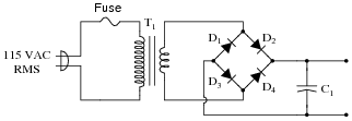
A technician builds a simple half-wave rectifier circuit for a project, but is surprised to find that the diode keeps failing:
|
|
This comes as a surprise because the diode has a repetitive peak reverse voltage rating of 50 volts, which the technician knows is greater than the peak voltage output by the step-down transformer. However, the technician has overlooked something very important in this circuit design. Explain what the problem is, and how to solve it.
Follow-up question: suggest a part number for a diode capable of withstanding the reverse voltage generated by this circuit, and able to handle at least 1 amp of continuous current.
Notes:
If students experience difficulty calculating the necessary PIV rating for this circuit's diode, ask them to analyze the peak output from the transformer's secondary winding for each half-cycle of the AC waveform, noting the voltage drops across all circuit components. Once a full-cycle voltage analysis is performed for all circuit components, the necessary diode rating should become obvious.
Though it may not be obvious at first reading, this question may actually serve as a lead-in for discussing voltage multiplier circuits. The fact that the diode experiences a reverse voltage twice that of the peak AC voltage is something we may exploit!
Another reliability factor most students won't recognize in this circuit is the ïnrush" current experienced by the diode every time the circuit is powered up and the capacitor recharges. Certainly, the diode was not properly rated for the reverse voltage it was being subjected to, but this might not be the only form of abuse! If time permits, discuss this possibility as well.
Question 3:
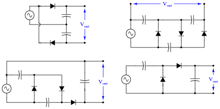
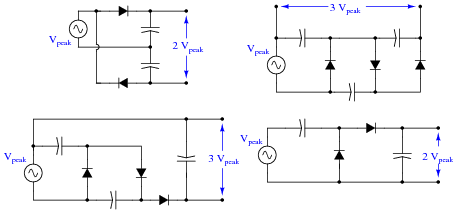
Diodes and capacitors may be interconnected to form a type of circuit that boosts voltage in the process of rectification. This type of circuit is generally known as a voltage multiplier. Shown here are a few different voltage multiplier circuits:
|
|
Determine the degree of voltage multiplication (double, triple, etc.) provided by each circuit.
|
|
Notes:
Ask your students how they analyzed each of these voltage multiplier circuits, and to explain their technique(s) to the rest of the class during discussion.
Question 4:
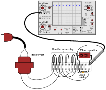
Suppose a technician measures the voltage output by an AC-DC power supply circuit:
|
|
The waveform shown by the oscilloscope is mostly DC, with just a little bit of AC "ripple" voltage appearing as a ripple pattern on what would otherwise be a straight, horizontal line. This is quite normal for the output of an AC-DC power supply.
Suppose we wished to take a closer view of this "ripple" voltage. We want to make the ripples more pronounced on the screen, so that we may better discern their shape. Unfortunately, though, when we decrease the number of volts per division on the "vertical" control knob to magnify the vertical amplification of the oscilloscope, the pattern completely disappears from the screen!
Explain what the problem is, and how we might correct it so as to be able to magnify the ripple voltage waveform without having it disappear off the oscilloscope screen.
Follow-up question: predict the frequency of the ripple voltage in this power supply circuit.
Notes:
As usual, what I'm looking for in an answer here is an explanation for what is happening. If a student simply tells you, "the vertical input is DC-coupled," press them for more detail. What does it mean for the input to be "DC-coupled," and why does this cause the line to disappear from the screen when we increase the vertical sensitivity? What alternative do we have to "DC coupling" on an oscilloscope?
One nice thing about oscilloscopes is that they cannot be damaged by "pegging" the display, as can analog multimeters. The same concept applies, though, and is useful in explaining to students why waveforms disappear from the screen when the vertical sensitivity is too great.
Question 5:
AC-DC power supply circuits are one of the most common circuit configurations in electronic systems. Though designs may vary, the task of converting AC power to DC power is vital in the functioning of a great many electronic devices.
Why is this? What is it about this kind of circuit that makes it such a necessary part of many electronic systems?
Notes:
One factor not mentioned in the answer is circuit operating voltage. How do the operating voltages of a typical AC power system and a typical electronic circuit (radio, alarm clock, computer) compare? Ask your students what purpose a power supply has with regard to voltage.
Ask your students if the word ßupply" is truly appropriate for this type of circuit. Does it really supply energy, or does it just convert energy from one form into another?
Question 6:
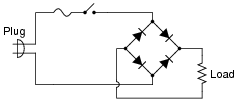
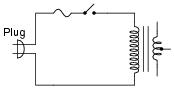
Although not a popular design, some power supply circuits are transformerless. Direct rectification of AC line power is a viable option in some applications:
|
|
However, this form of AC-to-DC power conversion has some significant limits. Explain why most power supply circuits utilize a transformer instead of directly rectifying the line power as this circuit does.
Follow-up question: explain in detail how the issue of non-isolation could create a safety hazard if this rectifier circuit were energized by an earth-grounded AC line circuit.
Notes:
Many old television sets used such transformerless rectifier circuits to save money, but this meant the metal circuit chassis inside the plastic cover was energized rather than being at ground potential! Very dangerous for technicians to work on.
Question 7:
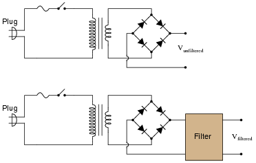
An essential part of an AC-DC power supply circuit is the filter, used to separate the residual AC (called the "ripple" voltage) from the DC voltage prior to output. Here are two simple AC-DC power supply circuits, one without a filter and one with:
|
|
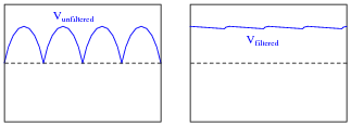
Draw the respective output voltage waveforms of these two power supply circuits (Vunfiltered versus Vfiltered). Also identify the type of filter circuit needed for the task (low pass, high pass, band pass, or band stop), and explain why that type of filter circuit is needed.
|
|
A low pass filter is the kind needed to filter "ripple voltage" from the power supply output.
Notes:
Many years ago, when I was first learning about power supplies, I tried to power an automotive radio with voltage from a battery charger. The battery charger was a simple power supply suitable for charging 12-volt automotive batteries, I reasoned, so what harm would there be in using it to power an automotive radio? After a few moments of LOUD humming from the radio speaker, my rhetorical question was answered by a puff of smoke from the radio, then silence.
Part of the problem was the output voltage of the battery charger, but a large part of the problem was the fact that the charger's output was unfiltered as well. For the same reasons my radio did not function properly on unfiltered, rectified AC, many electronic circuits will not function on it either.
Question 8:
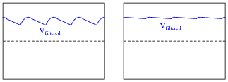
Observe the following two waveforms, as represented on an oscilloscope display measuring output voltage of a filtered power supply:
|
|
If both of these waveforms were measured on the same power supply circuit, at different times, determine which waveform was measured during a period of heavier "loading" (a "heavier" load being defined as a load drawing greater current).
Notes:
Ask your students what the term "loading" means in this context. Some of them may not comprehend the term accurately, and so it is good to review just to make sure.
More importantly, discuss with your students why the ripple is more severe under conditions of heavy loading. What, exactly, is happening in the circuit to produce this kind of waveform? If it is necessary for us to maintain a low amount of ripple under this heavy loading, what must we change in the power supply circuit?
Question 9:
What does it mean if a power supply has a DC output with 5% ripple?
Notes:
The purpose of this question is to get students to look up the formula for calculating ripple voltage percentage. Notice how I did not simply ask them to regurgitate a formula; rather, I presented a realistic figure for them to interpret. When at all possible, try to format your questions in this sort of practical context!
Question 10:
What parameters determine the frequency of a power supply's ripple voltage?
Notes:
Note that I did not simply say the ripple frequency is equal to line frequency for half-wave rectification and double the line frequency for full-wave. Such an answer is misleading, since it completely ignores polyphase AC rectification!
Question 11:
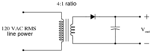
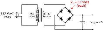
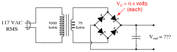
Suppose a power supply is energized by an AC source of 119 V RMS. The transformer step-down ratio is 8:1, it uses a full-wave bridge rectifier circuit with silicon diodes, and the filter is nothing but a single electrolytic capacitor. Calculate the unloaded DC output voltage for this supply (assume 0.7 volts drop across each diode). Also, write an equation solving for DC output voltage (Vout), given all these parameters.
|
Where,
Vout = DC output voltage, in volts
Vin = AC input voltage, in volts RMS
r = Transformer step-down ratio
Vf = Forward voltage drop of each diode, in volts
Follow-up question: algebraically manipulate this equation to solve for Vin.
Notes:
It is important for students to understand where this equation comes from. Ask your students to explain, step by step, the process of calculating output voltage for a simple power supply circuit. It is helpful in this process to calculate the voltage at each ßtage" of the power supply (transformer primary, transformer secondary, etc.), as though we were building the circuit one component at a time.
Incidentally, the method of building a project (such as a power supply) in a step-by-step fashion rather than all at once, saves a lot of time and effort when things go wrong. The same ßtep-by-step" strategy works well for mathematical analysis, and other problem-solving tasks as well: try to analyze the circuit one "block" at a time instead of the whole thing at once.
Question 12:
What does it mean if a power supply exhibits 2% voltage regulation?
Notes:
The purpose of this question is to get students to look up the formula for calculating voltage regulation percentage. Notice how I did not simply ask them to regurgitate a formula; rather, I presented a realistic figure for them to interpret. When at all possible, try to format your questions in this sort of practical context!
Question 13:
What will be the consequence of one diode failing open in the bridge rectifier of a single-phase power supply?
Notes:
A question such as this is best discussed while viewing the schematic diagram for a bridge rectifier. I recommend projecting an image of a bridge rectifier circuit on a whiteboard, then having students use dry-erase markers to "mark up" the schematic with arrows for current, voltage drop indications, etc. This way, mistakes can be corrected, or alternate cycles erased and re-drawn, without having to erase and re-draw the schematic diagram itself.
Question 14:
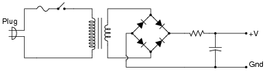
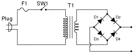
Suppose you suspected a failed-open diode in this power supply circuit. Describe how you could detect its presence without using an oscilloscope:
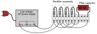
|
|
Incidentally, the "low voltage AC power supply" is nothing more than a step-down transformer with a center-tapped secondary winding.
Notes:
A common tendency for students is to troubleshoot using the ßhotgun approach," which is to remove each component one-by-one and test it. This is a very time-intensive and inefficient method of troubleshooting. Instead, students need to develop diagnostic procedures not requiring removal of components from the circuit. At the very least, there should be some way we can narrow the range of possibilities using in-circuit tests prior to removing components.
Question 15:
A student learns that a rectifier circuit is often followed by a low-pass filter circuit in an AC-DC power supply to reduce "ripple" voltage on the output. Looking over his notes from AC theory, the student proceeds to build this power supply circuit complete with a low-pass filter at the output:
|
|
While this design will work, there are better filter configurations for this application. Describe the limitations of the circuit shown, and explain how some of the other filters would do a better job.
Follow-up question: in some applications - especially where very large filter capacitors are used - it is a good idea to place a series resistor before the capacitor. Such a resistor is typically rated at a low value so as to not cause excessive output voltage ßag" under load, but its resistance does serve a practical purpose. Explain what this purpose might be.
Notes:
Challenge your students with this question: is this the right kind of filter circuit (low pass, high pass, band pass, band stop) to be using, anyway? This question presents a good opportunity to review basic filter theory.
The follow-up question asks students to think carefully about the possible positive benefits of having a series resistor before the capacitor as shown in the student's original design. If your students are experiencing difficulty understanding why a resistor would ever be necessary, jog their memories with this formula:
|
Question 16:
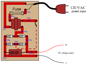
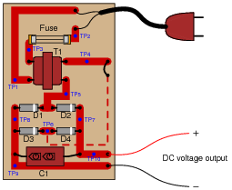
Identify the voltages that are supposed to appear between the listed test points:
|
|
- 1.
- VTP1-TP2 =
- 2.
- VTP1-TP3 =
- 3.
- VTP2-TP3 =
- 4.
- VTP4-TP5 =
- 5.
- VTP5-TP6 =
- 6.
- VTP7-TP8 =
- 7.
- VTP9-TP10 =
Assume that the power transformer has a step-down ratio of 9.5:1.
- 1.
- VTP1-TP2 = 120 volts AC
- 2.
- VTP1-TP3 = 120 volts AC
- 3.
- VTP2-TP3 = 0 volts
- 4.
- VTP4-TP5 = 12.63 volts AC
- 5.
- VTP5-TP6 = 12.63 volts AC
- 6.
- VTP7-TP8 = 16.47 volts DC
- 7.
- VTP9-TP10 = 16.47 volts DC
Notes:
Before one can troubleshoot a malfunctioning circuit, one must know what voltages and currents are supposed to be in various portions of the circuit. This question, therefore, is a prelude to further troubleshooting questions.
Question 17:
A technician is troubleshooting a power supply circuit with no DC output voltage. The output voltage is supposed to be 15 volts DC:
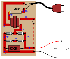
|
|
The technician begins making voltage measurements between some of the test points (TP) on the circuit board. What follows is a sequential record of his measurements:
- 1.
- VTP9-TP10 = 0 volts DC
- 2.
- VTP8-TP7 = 0 volts DC
- 3.
- VTP8-TP5 = 0 volts DC
- 4.
- VTP6-TP7 = 0 volts DC
- 5.
- VTP4-TP5 = 0 volts AC
- 6.
- VTP1-TP3 = 0 volts AC
- 7.
- VTP1-TP2 = 116 volts AC
Based on these measurements, what do you suspect has failed in this supply circuit? Explain your answer. Also, critique this technician's troubleshooting technique and make your own suggestions for a more efficient pattern of steps.
Follow-up question: with regard to the troubleshooting technique, this technician seems to have started from one end of the circuit and moved incrementally toward the other, checking voltage at almost every point in between. Can you think of a more efficient strategy than to start at one end and work slowly toward the other?
Notes:
Troubleshooting scenarios are always good for stimulating class discussion. Be sure to spend plenty of time in class with your students developing efficient and logical diagnostic procedures, as this will assist them greatly in their careers.
Question 18:
A technician is troubleshooting a power supply circuit with no DC output voltage. The output voltage is supposed to be 15 volts DC:

|
|
The technician begins making voltage measurements between some of the test points (TP) on the circuit board. What follows is a sequential record of her measurements:
- 1.
- VTP1-TP2 = 118 volts AC
- 2.
- VTP3-TP2 = 0 volts AC
- 3.
- VTP1-TP3 = 118 volts AC
- 4.
- VTP4-TP5 = 0.5 volts AC
- 5.
- VTP7-TP8 = 1.1 volts DC
- 6.
- VTP9-TP10 = 1.1 volts DC
Based on these measurements, what do you suspect has failed in this supply circuit? Explain your answer. Also, critique this technician's troubleshooting technique and make your own suggestions for a more efficient pattern of steps.
Follow-up question #1: with regard to the troubleshooting technique, this technician seems to have started from one end of the circuit and moved incrementally toward the other, checking voltage at almost every point in between. Can you think of a more efficient strategy than to start at one end and work slowly toward the other?
Challenge question: based on the voltage measurements taken, which do you think is the more likely failure, an open primary winding or an open secondary winding?
Follow-up question #2: how could you test the two windings of the transformer for a possible open fault? In other words, is there another type of measurement that could verify our hypothesis of a failed winding?
Notes:
Troubleshooting scenarios are always good for stimulating class discussion. Be sure to spend plenty of time in class with your students developing efficient and logical diagnostic procedures, as this will assist them greatly in their careers.
Students may be puzzled by the presence of DC voltage between TP7 and TP8, and also between TP9 and TP10 (1.1 volts), given that there is less than that amount of AC voltage at the rectifier's input. However, this is a common phenomenon with electrolytic capacitors, to "recover" a small voltage after having been discharged.
Question 19:
A technician is troubleshooting a power supply circuit with no DC output voltage. The output voltage is supposed to be 15 volts DC:

|
|
The technician begins making voltage measurements between some of the test points (TP) on the circuit board. What follows is a sequential record of his measurements:
- 1.
- VTP9-TP10 = 0 volts DC
- 2.
- VTP1-TP2 = 117 volts AC
- 3.
- VTP1-TP3 = 117 volts AC
- 4.
- VTP5-TP6 = 0 volts AC
- 5.
- VTP7-TP8 = 0.1 volts DC
- 6.
- VTP5-TP4 = 12 volts AC
- 7.
- VTP7-TP6 = 0 volts DC
Based on these measurements, what do you suspect has failed in this supply circuit? Explain your answer. Also, critique this technician's troubleshooting technique and make your own suggestions for a more efficient pattern of steps.
Follow-up question: with regard to the troubleshooting technique, this technician seems to have started from one end of the circuit and moved incrementally toward the other, checking voltage at almost every point in between. Can you think of a more efficient strategy than to start at one end and work slowly toward the other?
Notes:
Troubleshooting scenarios are always good for stimulating class discussion. Be sure to spend plenty of time in class with your students developing efficient and logical diagnostic procedures, as this will assist them greatly in their careers.
Question 20:
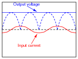
AC-DC power supplies are a cause of harmonic currents in AC power systems, especially large AC-DC power supplies used in motor control circuits and other high-power controls. In this example, I show the waveforms for output voltage and input current for an unloaded AC-DC power supply with a step-down transformer, full-wave rectifier, and capacitive filter circuit (the unfiltered DC voltage waveform is shown as a dashed line for reference):
|
|
As you can see, the input current waveform lags the voltage waveform by 90o, because when the power supply is unloaded, the only input current is the magnetizing current of the transformer's primary winding.
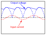
With increased loading, the output ripple voltage becomes more pronounced. This also changes the input current waveform significantly, making it non-sinusoidal. Trace the shape of the input current waveform, given the output voltage waveform and magnetizing current waveform (dotted line) shown here:
|
|
The non-filtered DC output waveform is still shown as a dotted line, for reference purposes.
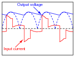
|
|
Challenge question: does the input current waveform shown here contain even-numbered harmonics (i.e. 120 Hz, 240 Hz, 360 Hz)?
Notes:
In a filtered DC power supply, the only time current is drawn from the rectifier is when the filter capacitor charges. Thus, the only time you see input current above and beyond the magnetizing current waveform is when the capacitor voltage requires charging.
Note that although the (sinusoidal) magnetizing current waveform is 90o out of phase with the voltage waveform, the input current transients are precisely in-phase with the current transients on the transformer's secondary winding. This reviews an important principle of transformers: that whatever primary current is the result of secondary winding load is in-phase with that secondary load current. In this regard, a transformer does not act as a reactive device, but a direct power-coupling device.
Note also that after the initial surge (rising pulse edge) of current, the input current waveform follows a different curve from the voltage waveform, because i = C[dv/dt] for a capacitor.
In case you haven't guessed by now, there is a lot of stuff happening in this circuit! I would consider this question to be ädvanced" for most introductory-level courses, and may be skipped at your discretion.
Question 21:
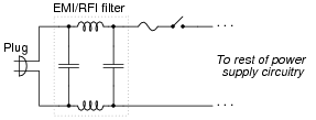
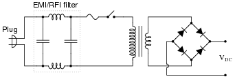
Power supplies are sometimes equipped with EMI/RFI filters on their inputs, to prevent high-frequency "noise" voltage created within the power supply circuit from getting back to the power source where it might interfere with other powered equipment. This is especially useful for ßwitching" power supply circuits, where transistors are used to switch power on and off very rapidly in the voltage transformation and regulation process:
|
|
Determine what type of filter circuit this is (LP, HP, BP, or BS), and also determine the inductive and capacitive reactances of its components at 60 Hz, if the inductors are 100 mH each and the capacitors are 0.022 mF each.
XC = 120.6 kW (each)
Notes:
Ask your students how they determined the identity of this filter. Are they strictly memorizing filter configurations, or do they have a technique for determining what type of filter circuit it is based on basic electrical principles (reactance of components to different frequencies)? Remind them that rote memorization is a very poor form of learning!
Question 22:
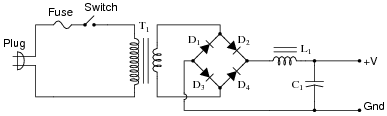
Complete this schematic diagram, turning it into a split (or dual power supply, with three output terminals: +V, Ground, and -V:
Notes:
Students need not provide details of voltage regulation, but merely show how AC from a center-tapped transformer winding may be rectified into two distinct DC outputs with a common "ground" connection.
Question 23:
Predict how all component voltages and currents in this circuit will be affected as a result of the following faults. Consider each fault independently (i.e. one at a time, no multiple faults):
|
|
- �
- Any one diode fails open:
- �
- Transformer secondary winding fails open:
- �
- Inductor L1 fails open:
- �
- Capacitor C1 fails shorted:
For each of these conditions, explain why the resulting effects will occur.
- �
- Any one diode fails open: Half-wave rectification rather than full-wave, less DC voltage across load, more ripple (AC) voltage across load.
- �
- Transformer secondary winding fails open: no voltage or current on secondary side of circuit after C1 discharges through load, little current through primary winding.
- �
- Inductor L1 fails open: no voltage across load, no current through load, no current through rest of secondary-side components, little current through primary winding.
- �
- Capacitor C1 fails shorted: increased current through both transformer windings, increased current through diodes, increased current through inductor, little voltage across or current through load, capacitor and all diodes will likely get hot.
Notes:
The purpose of this question is to approach the domain of circuit troubleshooting from a perspective of knowing what the fault is, rather than only knowing what the symptoms are. Although this is not necessarily a realistic perspective, it helps students build the foundational knowledge necessary to diagnose a faulted circuit from empirical data. Questions such as this should be followed (eventually) by other questions asking students to identify likely faults based on measurements.
Question 24:
Suppose this power supply circuit was working fine for several years, then one day failed to output any DC voltage at all:
|
|
When you open the case of this power supply, you immediately notice the strong odor of burnt components. From this information, determine some likely component faults and explain your reasoning.
Notes:
Troubleshooting scenarios are always good for stimulating class discussion. Be sure to spend plenty of time in class with your students developing efficient and logical diagnostic procedures, as this will assist them greatly in their careers.
Remind your students that test instrument readings are not the only viable source of diagnostic data! Burnt electronic components usually produce a strong and easily-recognized odor, always indicative of overheating. It is important to keep in mind that often the burnt component is not the original source of trouble, but may be a casualty of some other component fault.
Question 25:
The ripple frequency of a half-wave rectifier circuit powered by 60 Hz AC is measured to be 60 Hz. The ripple frequency of a full-wave rectifier circuit powered by the exact same 60 Hz AC line voltage is measured to be 120 Hz. Explain why the ripple frequency of the full-wave rectifier is twice that of the half-wave rectifier.
Notes:
I have heard students concoct very interesting (and wrong) explanations for why the two frequencies differ. One common misconception is that is has something to do with the transformer, as though a transformer had the ability to step frequency up and down just as easily as voltage or current! If students are not understanding why there is a frequency difference, you might want to help them out by asking two students to come up to the front of the class and draw two waveforms: half-wave and full-wave, along with their original AC (unrectified) waveforms.
Question 26:
Calculate the approximate DC output voltage of this power supply when it is not loaded:
|
|
Notes:
Ask your students to explain how they solved for this output voltage, step by step.
Question 27:
Calculate the approximate DC output voltage of this power supply when it is not loaded:
|
|
Notes:
Ask your students to explain how they solved for this output voltage, step by step.
Question 28:
A simple AC-DC power supply circuit outputs about 6.1 volts DC without a filter capacitor connected, and about 9.3 volts DC with a filter capacitor connected:
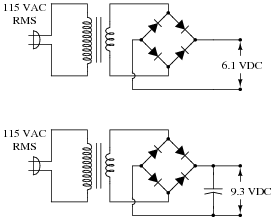
Explain why this is. How can the addition of nothing but a capacitor have such a great effect on the amount of DC voltage output by the circuit?
Notes:
Many new students find this phenomenon paradoxical, especially when they see a DC output voltage greater than the AC (RMS) output voltage of the transformer's secondary winding. Case in point: being able to build a 30 volt DC power supply using a transformer with a secondary voltage rating of only 24 volts. The purpose of this question is to get students to face this paradox if they have not recognized and resolved it already.
Question 29:
A technician is troubleshooting a power supply circuit that outputs substantially less DC voltage than it should. The output voltage is supposed to be 15 volts DC, but instead it is actually outputting less than 8 volts DC:
|
|
The technician measures approximately 18 volts AC (RMS) across the secondary winding of the transformer. Based on this voltage measurement and the knowledge that there is reduced DC output voltage, identify two possible faults that could account for the problem and all measured values in this circuit, and also identify two circuit elements that could not possibly be to blame (i.e. two things that you know must be functioning properly, no matter what else may be faulted). The circuit elements you identify as either possibly faulted or properly functioning can be wires, traces, and connections as well as components. Be as specific as you can in your answers, identifying both the circuit element and the type of fault.
- �
- Circuit elements that are possibly faulted
- 1.
- 2.
- �
- Circuit elements that must be functioning properly
- 1.
- 2.
Notes:
Troubleshooting scenarios are always good for stimulating class discussion. Be sure to spend plenty of time in class with your students developing efficient and logical diagnostic procedures, as this will assist them greatly in their careers.
Question 30:
A technician is troubleshooting a power supply circuit with no DC output voltage. The output voltage is supposed to be 15 volts DC, but instead it is actually outputting nothing at all (zero volts):
|
|
The technician measures 120 volts AC between test points TP1 and TP3. Based on this voltage measurement and the knowledge that there is zero DC output voltage, identify two possible faults that could account for the problem and all measured values in this circuit, and also identify two circuit elements that could not possibly be to blame (i.e. two things that you know must be functioning properly, no matter what else may be faulted). The circuit elements you identify as either possibly faulted or properly functioning can be wires, traces, and connections as well as components. Be as specific as you can in your answers, identifying both the circuit element and the type of fault.
- �
- Circuit elements that are possibly faulted
- 1.
- 2.
- �
- Circuit elements that must be functioning properly
- 1.
- 2.
Notes:
Troubleshooting scenarios are always good for stimulating class discussion. Be sure to spend plenty of time in class with your students developing efficient and logical diagnostic procedures, as this will assist them greatly in their careers.
Question 31:
A common sub-circuit in power supplies of all kinds is an EMI/RFI filter. This LC network is all but "transparent" to the 50 or 60 Hz power line frequency, so that the transformer sees full line voltage at all times:
|
|
If this EMI/RFI filter does nothing to or with the line power, what purpose does it serve?
Follow-up question: calculate the total inductive reactance posed by the two inductors to 60 Hz power if the inductance of each is 100 mH.
Notes:
These filters are very common in switch-mode power supplies, but they are not out of place in linear ("brute-force") power supply circuits such as this one. Mention to your students how the abatement of electromagnetic and radio frequency interference is a high priority in all kinds of electronic device design.