Switches
Question 1:
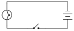
What is the purpose of the switch shown in this schematic diagram?
|
|
Notes:
Beginning students often find the terminology for switches confusing, because the words open and closed sound similar to the terminology used for doors, but do not mean quite the same thing when used in reference to a switch! In order to help avoid confusion, ask the students how they may think of these terms in a way that is consistent with their meaning in the context of an electrical switch.
One analogy to use for the switch's function that makes sense with the schematic is a drawbridge: when the bridge is down (closed), cars may cross; when the bridge is up (open), cars cannot.
Question 2:
How is an electrical switch constructed? What goes on inside the switch that actually "makes" or "breaks" a path for electric current?
Notes:
An inexpensive type of switch I use for teaching basic electricity/electronics classes is a household light switch. Available from hardware stores for very little cost, these switches are rugged and easy to connect into real circuits, large or small. For this question, you might want to let students disassemble one or two of these switches to observe how they are constructed.
This question is also a good point to start a conversation on the reliability of switches. Being that it has moving parts, what could possibly fail in a switch? How about the contacts themselves: what might happen to them over time, especially if överloaded" with too much electrical current?
Question 3:
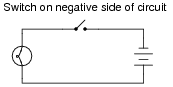
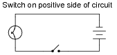
What difference will it make if the switch is located in either of these two alternate locations in the circuit?
|
|
|
|
Notes:
This is a difficult concept for some students to master. Make sure they all understand the nature of electrical current and the importance of continuity throughout the entire circuit. Perhaps the best way for students to master this concept is to actually build working battery-switch-lamp circuits. Remind them that their "research" of these worksheet questions is not limited to book reading. It is not only valid, but preferable for them to experiment on their own, so long as the voltages are low enough that no shock hazard exists.
One analogy to use for the switch's function that makes sense with the schematic is a drawbridge: when the bridge is down (closed), cars may cross; when the bridge is up (open), cars cannot.
Question 4:
Does this switch (in the closed state) have a low resistance or a high resistance between its terminals?

|
|
Notes:
Ask the students what it would mean if a closed switch actually measured having high resistance between its terminals. Knowing what the measurements of any electrical component ought to be is a very important skill for troubleshooting.
Question 5:
How might you use a meter (or a conductivity/continuity tester) to determine whether this electrical switch is in the open or closed state?

|
|
Notes:
This is another question which lends itself well to experimentation. A vitally important skill for students to develop is how to use their test equipment to diagnose the states of individual components.
An inexpensive source of simple (SPST) switches is a hardware store: use the same type of switch that is used in household light control. These switches are very inexpensive, rugged, and come with heavy-duty screw terminals for wire attachment. When used in small battery-powered projects, they are nearly indestructible!
Question 6:
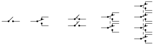
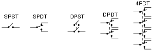
Identify the following types of switches, according to the number of "poles" and "throws" each switch has:
|
|
|
|
Notes:
Switches come in all types and sizes, and it is important for students to recognize certain common switch types, both by name and by schematic symbol.
Question 7:
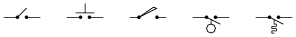
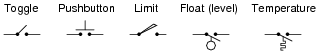
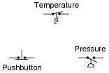
Identify the following types of switches, according to their style of actuation (how each switch is physically operated):
|
|
|
|
Notes:
Students will probably want to know how the temperature switch actually works. Be prepared to explain how bi-metallic elements may be used to actuate small mechanisms like switches, or challenge the students to research this on their own.
Question 8:
What type of switch is represented by this schematic symbol?

|
|
Notes:
Selector switches are very, very common in electrical and electronic circuits, for selecting different machine functions.
Question 9:
What type of switch is represented by this schematic symbol?

|
|
Notes:
Selector switches are very, very common in electrical and electronic circuits, for selecting different machine functions. Make-before-break switches are usually used where it is imperative to maintain continuity through the switch which switching between different positions.
Question 10:
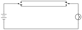
What positions do the switches have to be in for the light bulb to receive power?
|
|
Notes:
This wiring arrangement ("three-way" switches) is commonly used in residential lighting, for controlling a light bulb in a hallway with switches at either end. Once students relate this circuit to personal experience, it usually makes a lot more sense to them.
Question 11:
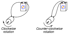
Electric motors of the permanent magnet design are very simple to reverse: just switch the polarity of the DC power to the motor, and it will spin the other direction:
|
|
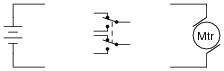
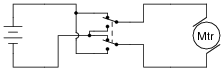
Complete this schematic diagram, showing how a DPDT switch may be placed in this circuit to reverse the motor's direction of rotation without the need to disconnect and re-connect wires:
|
|
|
|
Notes:
DPDT switches are often used as polarity-reversal devices. No doubt your students will see (or build!) this switch arrangement some time in their careers.
Question 12:
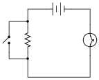
What will the light bulb do when the switch is open, and when the switch is closed?

|
|
Notes:
This is another opportunity to review the meanings of öpen" and "closed" with regard to switches. Again, students new to electricity often exhibit confusion over these terms, because in the context of doors they hold opposite meanings.
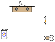
Question 13:
Examine this schematic diagram:
|
|
Now, without moving the following components, show how they may be connected together with wires to form the same circuit depicted in the schematic diagram above:
|
|
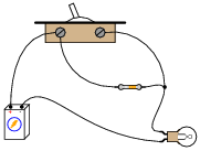
|
|
Notes:
One of the more difficult skills for students to develop is the ability to translate a nice, neat schematic diagram into a messy, real-world circuit, and visa-versa. Developing this skill requires lots of practice.
It is very worthwhile for students to discuss how they solve problems such as these with each other. For those students who have trouble visualizing shapes, a simple hint or "trick" to use when translating schematics to illustrations or visa-versa may be invaluable.
Question 14:
What does the normal status of an electrical switch refer to? Specifically, what is the difference between a normally-open switch and a normally-closed switch?
Notes:
An important qualification for an electrical switch to be either "normally-open" or "normally-closed" is that it have a spring to return it to its "normal" state in the absence of an actuating force. Latching switches such as most toggle switches really cannot be defined in terms of "normally-" anything. Discuss this with your students, possibly showing them some examples of momentary contact switches that are either N.O. or N.C.
Question 15:
Identify the "normal" status of each switch, whether it is normally-open (N.O.) or normally-closed (N.C.):
|
|
Based on the symbols shown, describe what physical condition results in the switch contacts being open, and what condition results in the switch contacts being closed, for each switch.
|
|
- �
- Temperature switch: cold = contacts closed, hot = contacts open
- �
- Pushbutton switch: unpressed = contacts closed, pressed = contacts open
- �
- Pressure switch: no applied pressure = contacts open, pressure applied = contacts closed
Notes:
Discuss with your students the different types of switches shown in this question (not just their normal status, but what physical event actuates each type of switch). There are many, many different types of switches - far more than just the types actuated by a human hand!
Question 16:
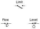
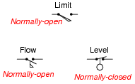
Identify the "normal" status of each switch, whether it is normally-open (N.O.) or normally-closed (N.C.):
|
|
Based on the symbols shown, describe what physical condition results in the switch contacts being open, and what condition results in the switch contacts being closed, for each switch.
|
|
- �
- Limit switch: untouched = contacts open, mechanical force = contacts closed
- �
- Flow switch: no fluid flow = contacts open, fluid flow = contacts closed
- �
- Level switch: dry (hanging in air) = contacts closed, submerged = contacts open
Notes:
Discuss with your students the different types of switches shown in this question (not just their normal status, but what physical event actuates each type of switch). There are many, many different types of switches - far more than just the types actuated by a human hand!
Question 17:
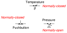
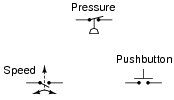
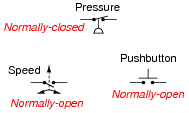
Identify the "normal" status of each switch, whether it is normally-open (N.O.) or normally-closed (N.C.):
|
|
Based on the symbols shown, describe what physical condition results in the switch contacts being open, and what condition results in the switch contacts being closed, for each switch.
|
|
- �
- Pressure switch: no applied pressure = contacts closed, pressure applied = contacts open
- �
- Speed switch: no motion = contacts open, motion = contacts closed
- �
- Pushbutton switch: unpressed = contacts open, pressed = contacts closed
Notes:
Discuss with your students the different types of switches shown in this question (not just their normal status, but what physical event actuates each type of switch). There are many, many different types of switches - far more than just the types actuated by a human hand!
Question 18:
Find one or two real switches and bring them with you to class for discussion. Identify as much information as you can about your switches prior to discussion:
- �
- Number of poles
- �
- Number of throws
- �
- Voltage rating of contacts
- �
- Current rating of contacts
- �
- Contact status for various actuator positions
- �
- Type (toggle, pushbutton)
Notes:
The purpose of this question is to get students to kinesthetically interact with the subject matter. It may seem silly to have students engage in a ßhow and tell" exercise, but I have found that activities such as this greatly help some students. For those learners who are kinesthetic in nature, it is a great help to actually touch real components while they're learning about their function. Of course, this question also provides an excellent opportunity for them to practice interpreting component markings, poles and throws, use a multimeter, access datasheets, etc.