Step-up, step-down, and isolation transformers
Question 1:
Calculate the voltage output by the secondary winding of a transformer if the primary voltage is 35 volts, the secondary winding has 4500 turns, and the primary winding has 355 turns.
Vsecondary =
Notes:
Transformer winding calculations are simply an exercise in mathematical ratios. If your students are not strong in their ratio skills, this question provides an application to sharpen them!
Question 2:
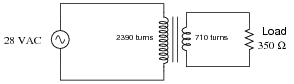
Calculate the load current and load voltage in this transformer circuit:
|
|
Iload = Vload =
Notes:
Most transformer problems are nothing more than ratios, but some students find ratios difficult to handle. Questions such as this are great for having students come up to the board in the front of the classroom and demonstrating how they obtained the results.
Question 3:
Calculate the number of turns needed in the secondary winding of a transformer to transform a primary voltage of 300 volts down to a secondary voltage of 180 volts, if the primary winding has 1150 turns of wire.
Nsecondary =
Notes:
Most transformer problems are nothing more than ratios, but some students find ratios difficult to handle. Questions such as this are great for having students come up to the board in the front of the classroom and demonstrating how they obtained the results.
Question 4:
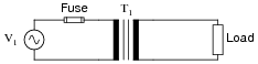
Predict how all component voltages and currents in this circuit will be affected as a result of the following faults. Consider each fault independently (i.e. one at a time, no multiple faults):
|
|
- �
- Transformer T1 primary winding fails open:
- �
- Transformer T1 primary winding fails shorted:
- �
- Transformer T1 secondary winding fails open:
- �
- Load fails shorted:
For each of these conditions, explain why the resulting effects will occur.
- �
- Transformer T1 primary winding fails open: No current through any component, no voltage across any secondary-side component.
- �
- Transformer T1 primary winding fails shorted: Large current through fuse (which will cause it to blow), little current through secondary winding or load, little voltage across secondary winding or load.
- �
- Transformer T1 secondary winding fails open: No current through any secondary-side component, no voltage across any secondary-winding component, little current through primary winding.
- �
- Load fails shorted: Large current through fuse (which will cause it to blow), large current through secondary winding and load, little voltage across secondary winding or load.
Notes:
The purpose of this question is to approach the domain of circuit troubleshooting from a perspective of knowing what the fault is, rather than only knowing what the symptoms are. Although this is not necessarily a realistic perspective, it helps students build the foundational knowledge necessary to diagnose a faulted circuit from empirical data. Questions such as this should be followed (eventually) by other questions asking students to identify likely faults based on measurements.
Question 5:
Suppose 1200 turns of copper wire are wrapped around one portion of an iron hoop, and 3000 turns of wire are wrapped around another portion of that same hoop. If the 1200-turn coil is energized with 15 volts AC (RMS), how much voltage will appear between the ends of the 3000-turn coil?
Notes:
Transformer winding calculations are simply an exercise in mathematical ratios. If your students are not strong in their ratio skills, this question provides an application to sharpen them!
Question 6:
Calculate the voltage output by the secondary winding of a transformer if the primary voltage is 230 volts, the secondary winding has 290 turns, and the primary winding has 1120 turns.
Vsecondary =
Notes:
Transformer winding calculations are simply an exercise in mathematical ratios. If your students are not strong in their ratio skills, this question provides an application to sharpen them!
Question 7:
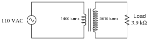
Calculate the source current and load current in this transformer circuit:
|
|
Isource = Iload =
Notes:
Most transformer problems are nothing more than ratios, but some students find ratios difficult to handle. Questions such as this are great for having students come up to the board in the front of the classroom and demonstrating how they obtained the results.
Question 8:
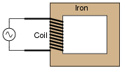
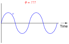
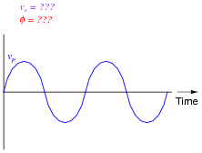
If a coil of insulated wire is wrapped around an iron core, an inductance will be formed. Even if the wire has negligible resistance, the current through the coil from an AC source will be limited by the inductive reactance (XL) of the coil, as the magnetic flux in the iron core oscillates back and forth to induce a counter-EMF:
|
|
Plot the instantaneous magnetic flux (f) waveform in the iron core corresponding to the instantaneous applied voltage (v) shown in this graph:
|
|
|
|
Notes:
There is a simple formula (albeit containing a derivative term) describing the relationship between instantaneous flux (f) and instantaneous induced voltage (v). Your students ought to know what it is, and that it should be applied to this question!
Question 9:
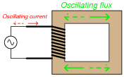
If we energize an inductor's coil with an oscillating (AC) voltage, we will generate an oscillating magnetic flux in the inductor core:
|
|
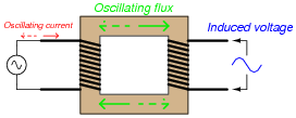
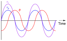
If we wrap a second coil of wire around the same magnetic core as the first (inductor) coil, we set up a situation where mutual inductance exists: a change of current through one coil induces a voltage in the other, and visa-versa. This, obviously, will result in an AC voltage being induced in the second wire coil:
|
|
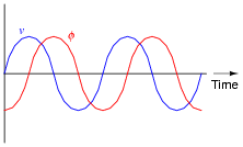
What name is given to such a device, with two coils of wire sharing a common magnetic flux? Also, plot both the magnetic flux waveform and the secondary (induced) voltage waveform on the same graph as the primary (applied) voltage waveform:
|
|
|
|
Note: the relative amplitudes of vp and vs are arbitrary. I drew them at different amplitudes for the benefit of the reader: so the two waveforms would not perfectly overlap and become indistinguishable from one another.
Notes:
Ask your students how the secondary coil would have to be made in order to truly generate a voltage greater than the applied (primary) coil voltage. How about generating a secondary voltage less than the primary?
Question 10:
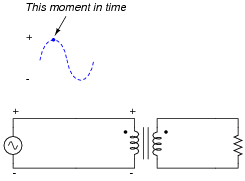
Shown here is a schematic diagram of a transformer powering a resistive load, at the exact moment in time where the primary winding's voltage is at its positive (+) peak:
|
|
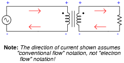
Identify the polarity of voltage across the load resistor at this exact moment in time, as well as the direction of current in each of the windings.
|
|
Follow-up question: note the relationship between direction of current and polarity of voltage for each of the transformer windings. What do these different relationships suggest, in regard to the "flow" of power in the circuit?
Notes:
One perspective that may help students understand the directions of current through each winding of the transformer, in relation to the voltage polarities, is to think of each winding as either being a source of electrical power or a load. Ask your students, "which winding acts as a source in this circuit, and which one acts as a load? Imagine these sources and loads are DC (so we may maintain the same polarity of voltage, for the sake of analysis). Which way would you draw the currents for a DC source and for a DC load?
Question 11:
The ignition coil of a gasoline-powered internal combustion automobile engine is an example of a transformer, although it is not powered by alternating current. Explain how a transformer may be operated on electricity that is not AC:

|
|
Challenge question: is the wave-shape of the secondary voltage sinusoidal? Why or why not?
Notes:
This is a very common application of transformer technology: the ignition "coil" used to ignite the air-fuel mixture inside a gasoline engine's combustion chamber. This question also addresses an issue sometimes misunderstood by students, that transformers are fundamentally AC devices, not DC.
It might be a good idea to have an automotive ignition coil available for for classroom demonstration. In lieu of a spark plug, a neon lamp may be used to indicate the presence of high voltage.
As for answering the challenge question, an oscilloscope will quickly prove the nature of the waveshape, for any transformer energized with pulsating DC.
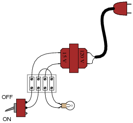
Question 12:
Something has failed in this circuit, because the light bulb does not light up when the switch is closed:
|
|
What type(s) of transformer fault(s) would cause a problem like this, and how might you verify using a multimeter?
Notes:
Of course, faults in this circuit having nothing to do with the transformer could also prevent the light bulb from lighting. If time permits, it would be good to analyze a few failure scenarios with your students, challenging them to locate the source of the trouble as efficiently as possible.
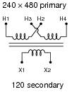
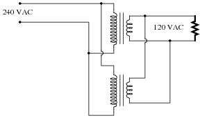
Question 13:
Industrial control power transformers are used to step down 480 or 240 volts to a level more acceptable for relay control circuitry: usually 120 volts. Some control power transformers are built with multiple primary windings, to facilitate connection to either a 480 volt or 240 volt AC power source:
|
|
Such transformers are usually advertised as having "240 × 480" primary windings, the "×" symbol representing two independent windings with four connection points (H1 through H4).
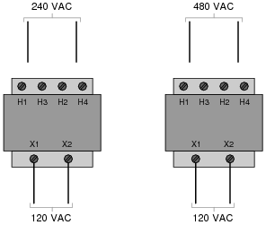
Show the connections on the four "H" terminals necessary for 240 volt operation, and also for 480 volt operation, on the following illustrations:
|
|
|
|
Notes:
This type of transformer is very common in industrial control systems. Discuss with your students why the primary winding terminals are arranged as they are (H1-H3-H2-H4), to facilitate near-terminal jumpering with metal clips.
Question 14:
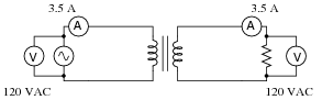
If an isolation transformer (a transformer with the same number of "turns" in the primary and secondary coils) is connected between an AC source and an AC load, we will measure the same voltage and the same current at both source and load terminals:
|
|
If we calculate power output by the source and power dissipated by the load, the value is the same: 420 Watts (P = IV).
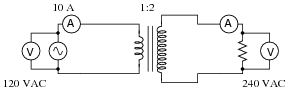
Now suppose we analyze a circuit containing a step-up transformer (one with more turns of wire in the secondary coil than in the primary coil). With a step-up transformer, the load voltage will be greater than the supply voltage. In this example, I show a step-up transformer with a 1:2 step ratio:
|
|
Assuming the load resistance is completely different from the first (isolation transformer) circuit, what can you deduce about the load current and the power (both source and load) in this circuit? Is the load current less than the source current? Is the load current greater than the source current? Is the load power greater than the source power? Explain your answers.
Notes:
The only reason I hesitate to tell students they can calculate load current precisely is because it was not stated whether or not the transformer is "lossy" at all. No real transformer is 100% lossless, of course, and this is something that we must take into consideration in "real life."
I have found that the Conservation of Energy approach not only makes sense to students as they learn to calculate transformer behavior, but it is an excellent reinforcement of a basic physical law, a good understanding of which will serve them well throughout their careers.
Question 15:
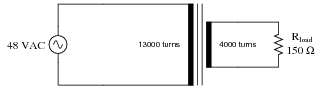
Calculate all listed values for this transformer circuit:
|
|
- �
- Vprimary =
- �
- Vsecondary =
- �
- Iprimary =
- �
- Isecondary =
Explain whether this is a step-up, step-down, or isolation transformer, and also explain what distinguishes the "primary" winding from the ßecondary" winding in any transformer.
- �
- Vprimary = 48 volts
- �
- Vsecondary = 14.77 volts
- �
- Iprimary = 30.3 mA
- �
- Isecondary = 98.5 mA
This is a step-down transformer.
Notes:
Most transformer problems are nothing more than ratios, but some students find ratios difficult to handle. Questions such as this are great for having students come up to the board in the front of the classroom and demonstrating how they obtained the results.
Question 16:
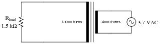
Calculate all listed values for this transformer circuit:
|
|
- �
- Vprimary =
- �
- Vsecondary =
- �
- Iprimary =
- �
- Isecondary =
Explain whether this is a step-up, step-down, or isolation transformer, and also explain what distinguishes the "primary" winding from the ßecondary" winding in any transformer.
- �
- Vprimary = 3.7 volts
- �
- Vsecondary = 12.0 volts
- �
- Iprimary = 26.1 mA
- �
- Isecondary = 8.02 mA
This is a step-up transformer.
Notes:
Most transformer problems are nothing more than ratios, but some students find ratios difficult to handle. Questions such as this are great for having students come up to the board in the front of the classroom and demonstrating how they obtained the results.
Note to your students how the distinction between a step-up and a step-down transformer is simply a matter of usage. It is possible to use a transformer either way!
Question 17:
In a typical step-up or step-down transformer, the higher-voltage winding usually uses finer gauge wire than the lower-voltage winding. Explain why this is.
Notes:
If you happen to have a transformer that has been cut in half (right through the core), it will make an excellent demonstration piece for discussion. The difference between windings will be immediately apparent to the students when they see one.
Question 18:
A mechanic goes to school and takes a course in AC electric circuits. Upon learning about step-up and step-down transformers, he makes the remark that "Transformers act like electrical versions of gears, with different ratios."
What does the mechanic mean by this statement? What exactly is a "gear ratio," and is this an accurate analogy for a transformer?
Notes:
Not only is this a sound analogy, but one that many mechanically-minded people relate with easily! If you happen to have some mechanics in your classroom, provide them with the opportunity to explain the concept of gear ratios to those students who are unaware of gear system mathematics.
Question 19:
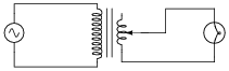
Explain how this special transformer is able to control power to the light bulb:
|
|
What advantages might there be to using a transformer to control AC power, as opposed to a variable resistor?
Note: a similar type of device is called a Variac, and it enjoys the same advantages of AC power control as the variable transformer shown in the question.
Notes:
It may help to give some numerical examples of voltage step-down ratio for the transformer in this circuit, for students to better understand how this device controls light bulb power. Remind your students that modern transformers are very efficient devices, with full-load efficiency ratings typically in excess of 95%.
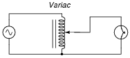
If students ask about the Variac, you may want to show them this diagram:
|
|
Of course, the Variac is a type of autotransformer, and as such does not provide the electrical isolation of a regular transformer. In some instances, this may be important!
Question 20:
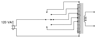
In this variable-voltage transformer circuit, the input voltage (120 VAC) is switched to different "taps" on the transformer's primary winding to create different step-down ratios.
|
|
While it is possible to "tap" the secondary winding of the transformer to achieve different output voltages instead of the primary, there is a good reason for locating the switch in the primary side of the circuit. Identify this practical reason.
Notes:
It is important to always keep in mind practical limitations of components such as switch contacts when designing circuits. Sure, there may be many alternative ways of building a working circuit, but some ways will be more practical than others.
In some cases, it might be better to locate the switch (and winding taps) on the secondary side of a step-down transformer rather than the primary. Imagine if the primary winding voltage was 100 kVAC instead of 120 VAC. Pose this scenario to your students and ask them what practical switch limitations might force re-location to the secondary winding of the transformer.
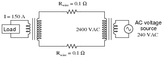
Question 21:
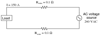
Suppose a power system were delivering AC power to a resistive load drawing 150 amps:
|
|
Calculate the load voltage, load power dissipation, the power dissipated by the wire resistance (Rwire), and the overall power efficiency (h = [(Pload)/(Psource)]).
- Eload =
- Pload =
- Plines =
- h =
Now, suppose we were to use a pair of perfectly efficient 10:1 transformers to step the voltage up for transmission, and back down again for use at the load. Re-calculate the load voltage, load power, wasted power, and overall efficiency of this system:
|
|
- Eload =
- Pload =
- Plines =
- h =
- Eload = 210 volts
- Pload = 31.5 kW
- Plines = 4.5 kW
- h = 87.5 %
Complex system (with transformers):
- Eload = 239.7 volts
- Pload = 35.96 kW
- Plines = 45 W
- h = 99.88 %
Follow-up question: can you think of any disadvantages of the circuit using 10:1 transformers compared to the original (transformerless) power system?
Notes:
An example like this usually clarifies the benefits of using AC instead of DC for transmission of large amounts of electrical power over substantial distances, better than simply telling students why transformers are used in power systems. Even with modest power losses in the transformers (say, 3% loss in each), the overall efficiency is still much greater in this system than without using transformers at all.
In discussing the follow-up question, be sure to bring up safety as a consideration if none of your students do.
Question 22:
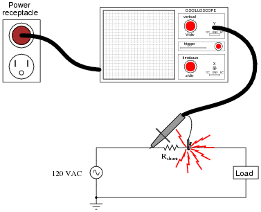
Shunt resistors are commonly used to measure current in power circuits, by producing a small voltage drop in direct proportion to the circuit current. They are especially useful for measuring complex current waveforms in AC circuits, since they do not distort the waveform at all.
Suppose you wished to measure the current waveform in this power circuit by using an oscilloscope to measure voltage dropped across the shunt resistor:
|
|
If you connect an oscilloscope to the power circuit as shown, very bad things will happen, like the oscilloscope's ground clip melting, with lots of sparks!
After replacing the damaged probe assembly, and taking a long break to soothe your nerves, an experienced technician suggests you plug the oscilloscope's power cord into an isolation transformer to avoid this problem in the future. Explain what an isolation transformer is, why it prevents the short-circuit problem experienced in this circuit, and what precautions must be taken when using one.
If an isolation transformer is used in such a way, it avoids the short-circuit problem, but only at the cost of üngrounding" the oscilloscope chassis, making it unsafe to touch!!!
Follow-up question: identify a way to safely use an oscilloscope to measure the shunt resistor's voltage, without having to use an isolation transformer.
Notes:
This lesson on oscilloscope usage is a valuable one, as students are sure to encounter problems with their circuits resulting from earth ground connections through the oscilloscope's chassis ground. Having an oscilloscope and an ohmmeter in the classroom during discussion time would be a good idea, so students may test the common connections themselves.
Question 23:
Suppose you need to power a 120 volt, 600 watt heating element from a 240 volt source. You happen to have several 240V/120V step-down transformers on hand, but each one is only rated at 400 VA. Draw a schematic diagram showing how multiple transformers could be used to match the 120 volt load to the 240 volt source.
|
|
Notes:
In case you students have not yet studied AC power (watts, volt-amps, and volt-amps reactive), let them determine what "VA" means first, and then let them know it is simply equivalent to "watts" for a resistive load.
It is a very realistic problem to have to match available components to a particular task, so this question is worth your students' while to discuss and understand thoroughly.
Question 24:
Explain how the construction of a step-down transformer differs from that of a step-up transformer.
Notes:
Ask your students to explain the relationship between primary and secondary turns, and how this affects the voltage transformation ratio, based on mutual inductance.
Question 25:
Explain how the construction of an isolation transformer differs from that of a step-up or step-down transformer.
Notes:
Ask your students to explain the relationship between primary and secondary turns, and how this affects the voltage transformation ratio, based on mutual inductance.
Question 26:
When calculating power in transformer circuits, how do the primary and secondary circuit powers (Pprimary = VprimaryIprimary and Psecondary = VsecondaryIsecondary) compare with each other? Is one greater than the other? If so, which one, and why?
Notes:
The simplest answer to this question is that Psecondary = Pprimary, and this is a useful principle when doing transformer circuit calculations. Even when it is not precisely true, it is still a useful tool for checking the veracity of our calculations. Ask your students why this is.
Question 27:
Explain why transformers are used extensively in long-distance power distribution systems. What advantage do they lend to a power system?
Notes:
Ask your students to explain the answer in detail, rather than just repeating what the given answer states. Why is high-voltage power distribution more efficient than low-voltage distribution? Why would high voltage have to be stepped down for point-of-use applications?
Question 28:
Are the transformers connecting power plant generators to high-voltage power lines considered step-up or step-down? Explain your answer.
Notes:
Ask your students to define ßtep-up" and ßtep-down" in reference to power system transformers.
Question 29:
A soldering gun is a tool used to quickly heat electrical connections for soldering. Too bulky for printed-circuit board (PCB) applications, it is better suited for point-to-point wiring applications where large wires are to be joined to metal lugs and to other wires.
In addition to being a useful soldering tool, this device is also an excellent example of a step-down transformer. Explain how the construction of a soldering gun employs a step-down transformer (with a very large step ratio!) to generate high temperatures at the soldering tip.
Notes:
For students lacking soldering guns to take apart, and for those who do not want to take any chances ruining a tool through improper disassembly/reassembly, it is not difficult to find photographs of soldering gun internals. The step-down transformer assembly should be obvious when inspected.
Question 30:
The circuit shown here has a problem: the lamp does not light up, even though the AC power source is known to be good. You know that the circuit used to work just fine, so it is designed properly. Something in it has failed:
|
|
Identify one component or wire fault that could account for the lamp not lighting, and describe how you would use test equipment to verify that fault.
- �
-
One failed wire or component in the circuit that could possibly account for the problem, and the type of fault (open or short) you suspect it would be.
- �
- Identify the type of test measurement you would take on this circuit, and where you would take it (identify the test points you would measure between) to verify the suspected fault.
Notes:
Of course, faults in this circuit having nothing to do with the transformer could also prevent the light bulb from lighting. If time permits, it would be good to analyze a few failure scenarios with your students, challenging them to locate the source of the trouble as efficiently as possible.
Question 31:
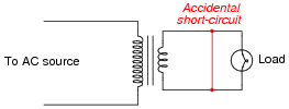
Suppose a step-down transformer fails due to an accidental short-circuit on the secondary (load) side of the circuit:
|
|
That the transformer actually failed as a result of the short is without any doubt: smoke was seen coming from it, shortly before current in the circuit stopped. A technician removes the burned-up transformer and does a quick continuity check of both windings to verify that it has failed open. What she finds is that the primary winding is open but that the secondary winding is still continuous. Puzzled at this finding, she asks you to explain how the primary winding could have failed open while the secondary winding is still intact, if indeed the short occurred on the secondary side of the circuit. What would you say? How is it possible that a fault on one side of the transformer caused the other side to be damaged?
Notes:
It is important for students to realize that a transformer "reflects" load conditions on the secondary side to the primary side, so that the source "feels" the load in all respects. What happens on the secondary (load) side will indeed be reflected on the primary (source) side.
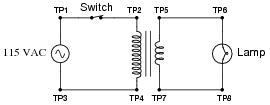
Question 32:
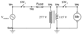
An AC motor receives reduced voltage through a step-down transformer so it may properly operate on a 277 volt source:
|
|
After years of trouble-free operation, something fails. Now, the motor refuses to operate when both switches are closed. A technician takes four voltage measurements between the following test points with both switches in the ön" position:
-
Step Measurement
1 VTP2-Gnd = 277 V
2 VTP3-Gnd = 277 V
3 VTP5-Gnd = 0 V
4 VTP4-Gnd = 0 V
Complete this expanded table, following the technician's steps in the same order as the voltage measurements were taken, labeling each component's status as either Ö" (possibly open), "S" (possibly shorted), or ÖK" (known to be good). The first row of the table should contain many possible fault labels (because with little data there are many possibilities), but as more measurements are taken you should be able to limit the possibilities. Assume that only one component is faulted.
-
Step Measurement SW1 Fuse Primary Secondary SW2 Motor
1 VTP2-Gnd = 277 V
2 VTP3-Gnd = 277 V
3 VTP5-Gnd = 0 V
4 VTP4-Gnd = 0 V
-
Step Measurement SW1 Fuse Primary Secondary SW2 Motor
1 VTP2-Gnd = 277 V OK O O O O O
2 VTP3-Gnd = 277 V OK OK O O O O
3 VTP5-Gnd = 0 V OK OK O O O OK
4 VTP4-Gnd = 0 V OK OK O O OK OK
Either the primary or the secondary winding is failed open!
Follow-up question: describe what you would measure next in this circuit to determine whether it is the primary or secondary winding that has failed open.
Notes:
Students may ask why it is possible for us to say that the second switch and motor are okay after the technician measured 0 volts before each. Certainly we know something has failed before the points where 0 volts is measured, but that does not tell us the health of components after those points! The answer to this very good question is the assumption stated at the end of the question: that we are to assume only one component fault in the circuit. If either switch 2 or the motor were failed open, it would still not account for a lack of voltage between TP4 and ground. A shorted motor might, but then the fuse would have blown, resulting in 0 volts between TP3 and ground. So, we assume the motor and switch 2 must be okay because only some other single fault could cause the measurements we are reading.
Question 33:
Ethernet is a popular communications standard for many digital devices, personal computers included. Originally, Ethernet was intended to be a network standard for conveying digital data only, without power. In later years, however, upgrades to the standard allowed DC power to be conveyed over the same wire pairs. The IEEE standard 802.3af is one example of a power-over-Ethernet standard.
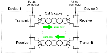
Shown here is a schematic showing how two Ethernet devices connect together over a Category 5 ("Cat 5") twisted-pair cable, with no DC power conveyed over the cabling:
|
|
Digital data consists of voltage pulses over time (AC, essentially), conducted between the two devices over two sets of twisted-pair wires.
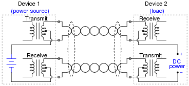
The next schematic shows the 802.3af standard allowing both DC power and digital data to be communicated over the same pairs of wires. Note the use of transformers at each device:
|
|
Explain what function(s) the transformers provide in this system, and how they allow DC power to travel through the wire pairs from source to load without interfering with the Ethernet data signals, which are AC.
Notes:
This is an interesting application of transformers: isolation of DC allowing a form of "power line carrier" system to be made without the use of filter networks.
Actually, there is more to the 802.3af standard than what is shown in the second schematic diagram. This standard also allows the use of the other two pairs of wires in Cat 5 cable as dedicated power conductors. I omit this aspect for simplicity.
Question 34:
Find one or two real transformers and bring them with you to class for discussion. Identify as much information as you can about your transformers prior to discussion:
- �
- Winding ratio(s)
- �
- Winding resistances
- �
- Voltage rating of each winding
- �
- Current rating of each winding
- �
- Frequency rating
- �
- Application (power, signal, audio, etc.)
- �
- Type (iron core, air core, etc.)
Be prepared to prove the actual winding resistances of your transformers in class, by using a multimeter!
Notes:
The purpose of this question is to get students to kinesthetically interact with the subject matter. It may seem silly to have students engage in a ßhow and tell" exercise, but I have found that activities such as this greatly help some students. For those learners who are kinesthetic in nature, it is a great help to actually touch real components while they're learning about their function. Of course, this question also provides an excellent opportunity for them to practice interpreting component markings, use a multimeter, access datasheets, etc.