Impedance matching with transformers
Question 1:
Suppose you were to take a 3 kW electric heater rated for 240 VAC and connect it to a 120 VAC power source. How much power would it dissipate when connected to a voltage source equal to half its rating?
Notes:
A common mistake students make is to think that applying half the normal amount of voltage to a resistor results in half the power dissipation. This is not correct. There are many ways to disprove the assertion mathematically, and I won't bother to list my favorite here. Discuss this with your students, and see what their reasoning is.
Question 2:
How much resistance must a heating element possess in order to dissipate 3 kW of power at 240 VAC? How much resistance must a heating element possess in order to dissipate the same amount of power (3 kW) at half the voltage (120 VAC)?
R120V = 4.8 W
Notes:
This question is an exercise in algebraic manipulation. Sure, students will be able to find an equation solving for resistance in terms of power and voltage, but for the sake of algebra practice they should be asked to derive the equation from a more common power equation, such as P = [(E2)/R].
Question 3:
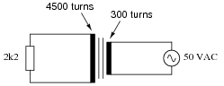
Calculate all voltages and all currents in this circuit, given the component values and the number of turns in each of the transformer's windings:
|
|
IR = 340.9 mA
Esource = 50 V
Isource = 5.114 A
Follow-up question: given the voltage and current figures of the power source, how much impedance does it "think" it is driving?
Notes:
This question checks students' ability to relate the winding ratio to voltage and current ratios in a transformer circuit. The symbolism here is common in Europe, but not so common in the United States.
Question 4:
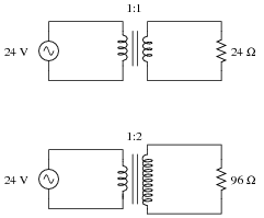
Calculate the amount of power supplied by the source in each of these circuits:
|
|
What do you notice about these two circuits that is interesting? How much impedance does each source "think" it is supplying power to, based on the following formula?
|
Notes:
I like using specific numerical examples to introduce the concept of impedance transformation, because I find abstract mathematical presentations tend to "lose" a lot of students.
Question 5:
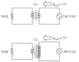
In each of these circuits, calculate the amount of load impedance ßeen" by the voltage sources given the turns ratio of each transformer:
|
|
Hint: ïmpedance" (Z) is defined mathematically as the ratio of voltage (E) to current (I).
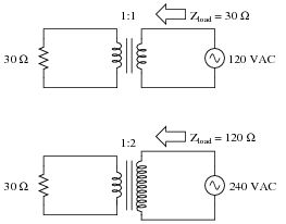
|
|
Notes:
The setup of this problem may confuse some students, with reference to the amount of impedance that a source ßees". Hopefully, the anthropomorphic language will not be a barrier to understanding. The point is, for students to realize that just as a load can have a voltage or a current ïmpressed" upon it, a source can have a load ïmpressed" upon it as well. In this particular question, the issue is how the 1:2 step-down transformer ratio affects the amount of loading impressed upon the 240 VAC source by the 30 ohm resistor. That the resistor ßees" the same source voltage should be obvious. That the sources see very different impedance loadings (due to the transformer) is the purpose of this question.
Question 6:
If a step-up transformer has a turns ratio of 3:1, calculate the following:
- �
- The voltage ratio (secondary:primary)
- �
- The current ratio (secondary:primary)
- �
- The winding inductance ratio (secondary:primary)
- �
- The load impedance ratio (secondary:primary)
What mathematical pattern(s) do you see between the turns ratio and these four ratios?
- �
- The voltage ratio (secondary:primary) = 3:1
- �
- The current ratio (secondary:primary) = 1:3
- �
- The winding inductance ratio (secondary:primary) = 9:1
- �
- The load impedance ratio (secondary:primary) = 9:1
Notes:
Determining the voltage and current ratios should be trivial. Calculating the impedance ratio will likely require the set-up of an example problem, based on known values of voltage and current.
The most important part of this question is the identification of mathematical patterns and trends relating the turns ratio to the requested ratios. Of particular note are the inductance and impedance ratios. Why are they 9:1 and not 3:1? Ask your students what mathematical operation relates the number 3 to the number 9? If necessary, have them work through another example problem (with a different turns ratio) to see the impedance transformation ratio there, and the resulting relationship between that ratio and the turns ratio.
Question 7:
A step-down transformer has a winding turns ratio of 20:1. Calculate the impedance ratio from primary to secondary. Also, determine the amount of impedance ßeen" at the primary winding if the secondary winding is connected to a 90 ohm load.
Impedance ratio = Zprimary =
Notes:
Most transformer problems are nothing more than ratios, but some students find ratios difficult to handle. Questions such as this are great for having students come up to the board in the front of the classroom and demonstrating how they obtained the results. In this particular case there is more to the solution than just a simple ratio, which is even more reason to have students show their different solution techniques!
Question 8:
What would happen to the impedance transformation ratio if a short-circuit developed between some of the turns in the 300-turn winding of this transformer? Explain your answer.
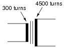
|
|
Notes:
This is somewhat of a "trick" question, because students are accustomed to equating a ßhort" with a decrease in impedance. While this is generally true, what we're talking about here is an impedance ratio, rather than any one impedance in particular.
Question 9:
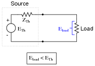
All electrical sources contain some internal impedance. This explains why voltage sources ßag" when placed under load:
|
|
In this diagram, the source's internal impedance has been "lumped" into a single component, labeled ZTh, the Thévenin impedance. This intrinsic impedance naturally limits the amount of power any source can deliver to a load. It also creates a condition where load power is optimized at a particular load impedance.
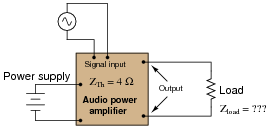
Determine the load impedance value necessary for maximum power dissipation, if powered by an audio amplifier circuit with an internal (Thévenin) impedance of 4 W.
|
|
Notes:
Discuss with your students the "Maximum Power Transfer Theorem" as it relates to this question.
Question 10:
An audio power amplifier with an internal impedance of 8 W needs to power a set of speakers with a combined total impedance of 1 W. We know that connecting this speaker array directly to the amplifier's output will not result in optimum power transfer, because of the impedance mismatch.
Someone suggests using a transformer to match the two disparate impedances, but what turns ratio does this transformer need to have? Should it be used in a step-up configuration, or a step-down configuration? Explain your answers.
Notes:
Students should know at this point how to calculate the impedance transformation ratio from a transformer's winding ratio. In this question, they are challenged to calculate "backwards" to find the winding ratio from the impedance ratio.
Question 11:
A mechanic goes to school and takes a course in AC electric circuits. Upon learning about step-up and step-down transformers, he makes the remark that "Transformers act like electrical versions of gears, with different ratios."
What does the mechanic mean by this statement? What exactly is a "gear ratio," and how does this relate to the subject of impedance matching?
The concept of ïmpedance" is just as valid in mechanical systems as in electrical systems: a "low impedance" mechanical load requires high speed and low torque, whereas a "high impedance" load requires high torque and low speed. Gear systems provide impedance matching between mechanical power sources and loads in the same way that transformers provide impedance matching between (AC) electrical power sources and loads.
Notes:
Not only is this a sound analogy, but one that many mechanically-minded people relate with easily! If you happen to have some mechanics in your classroom, provide them with the opportunity to explain the concept of gear ratios to those students who are unaware of gear system mathematics.
I normally do not elaborate this much in my answers, but in this case I believe it may be necessary, as this is quite a cognitive leap for some people. It is a leap well worth making, however, since it connects two (seemingly) disparate phenomenon in a way that provides a sound context for understanding the concept of impedance matching.
Question 12:
One of the practical uses of transformers is to adapt equipment to conditions not anticipated in their original design. For instance, a heating element (which is essentially nothing more than a resistor with an unusually high power dissipation rating) may need to be operated at a lower power dissipation than designed for.
For example, suppose you have a 1 kW electric heater rated for 208 volt operation, which you intend to operate at a reduced power dissipation of 750 watts. Calculate the proper amount of voltage you would need to achieve this reduced power dissipation, and explain how you could use a transformer to supply this reduced voltage to the heater.
Notes:
Some students may struggle in calculating the necessary voltage, because this problem does not exactly match most voltage/current/power calculations problems they've seen in the past. The necessary math is almost trivial, but the "trick" is applying well-known equations to something unfamiliar. This is an excellent opportunity to discuss problem-solving strategies, so be sure to have students share their ideas on how to solve for the necessary voltage.
Question 13:
Suppose you were using a 600 watt, 120 volt electric heater to pre-heat the oil in a hydraulic system, but determined later that this heater delivered too much heat to the oil. A 400 watt heater would be more appropriate for the task, but unfortunately another heater is not available in that power rating.
You realize that the power output of this 600 watt heater could be reduced by supplying it with less voltage. You also realize that a transformer could be used to reduce the AC voltage delivered to the heater without incurring the large power losses of a voltage-dropping resistor.
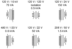
The following transformer types are available to use for the task:
|
|
Design a circuit that uses one or more of these transformers to reduce the line voltage (120 VAC) down to an appropriate level so that the 600 watt heater will only output (approximately) 400 watts.
There is more than one possible solution to this problem using the transformer types available. You should realize, though, that there is more to consider than just getting the right voltage. Equally important to the solution is the transformers' ability to handle the current demanded by the heater.
Notes:
A problem such as this is very realistic: having to engineer a solution to a practical dilemma with a limited choice of components. Let your students know that solving problems in real life involves creativity just as much as it involves mathematical calculations and other "closed form" (single right answer) methods.
Question 14:
A simple pair of audio headphones makes a remarkably sensitive and useful piece of test equipment for detecting signals in a wide variety of circuits. Even very small DC voltages may be detected with a pair of headphones, if you listen for a "click" sound when contact is made or broken between a voltage source and the headphone's test probes.

|
|
Yet, a plain pair of headphones is unsuitable for many test applications for two reasons:
- �
- Electrical safety
- �
- Low impedance
It is generally not a good idea to place your body in a position where it may come into direct contact with a live circuit, especially if that circuit harbors substantial voltages. Being that headphones are worn on a person's head, with the potential for electrical contact between one of the speaker elements and the wearer's head, this is quite possibly unsafe.
Secondly, the impedance of a high-quality headphone set is generally 8 ohms. While being a common audio speaker impedance, this low value would place far too great of a "burden" on many types of electronic circuits if directly connected. What is desired for a piece of test equipment is 1000 W or more.
Explain how a transformer may be inserted into the headphone test circuit in such a way as to address both these problems.

|
|
Follow-up question: even though a pair of headphones used in this manner cannot provide quantitative measurements of signals, there are some qualitative features which a skilled user may discern from the sounds produced. Describe what features of an AC signal may be detected with headphones, and how this compares to the information obtained from an oscilloscope.
Notes:
This question reviews both the principles of impedance matching and electrical isolation, in addition to exposing students to a novel and inexpensive piece of test equipment they can build on their own. I highly recommend making the construction and use of one of these devices a lab project in your curriculum. I use a headphone test set regularly in my own experimentation, and I have found it very useful in understanding AC phenomenon (especially if you do not have your own oscilloscope).
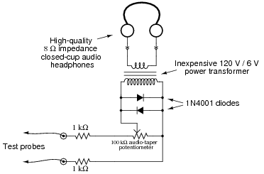
The circuit I recommend for students to build is this:
|
|
The 1 kW resistors and 1N4001 rectifying diodes provide protection against hearing damage, by limiting the voltage which may be applied to the primary winding of the transformer. The potentiometer, of course, provides volume control, while the transformer steps up the headphones' impedance and provides electrical isolation. I recommend a 120 volt power transformer for the task because it is rated for line voltage, and will surely provide the necessary isolation between circuit and headphones necessary for safety. A regular 8:1000 ohm äudio transformer" is not necessarily rated for the same (high) levels of voltage, and therefore would not provide the same margin of safety. For best performance, use a pair of headphones with the greatest ßensitivity" rating (measured in dB) possible.
Question 15:
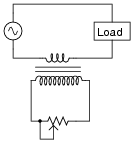
This is an interesting application of a transformer:
|
|
With this circuit, power to the AC load may be controlled by the variable resistor's setting:
|
|
Calculate the amount of series impedance the transformer places in the load current's path, if the variable resistor is set to a resistance of 15 ohms, and the winding ratio is 20:1.
Follow-up question identify any potential safety hazards associated with using a transformer in this capacity.
Notes:
Ask your students to think of a practical application for a circuit like this. Also, challenge them with this question: if the resistor were to open fully (� ohms), would current to the load completely stop? Why or why not?
Question 16:
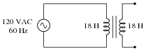
Calculate the primary winding current (magnitude and phase angle) for this unloaded isolation transformer, with primary and secondary inductances of 18 Henrys each:
|
|
Assume the winding inductances are "pure" (no resistive components).
Challenge question: what changes, if any, would result in the primary current value is this were not an isolation transformer, but rather a transformer where the secondary inductance was something other than 18 H?
Notes:
Students should realize from the answer that an unloaded transformer simply appears as an inductor to the source.
Question 17:
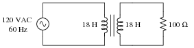
Calculate the primary winding current (magnitude and phase angle) for this resistively loaded isolation transformer, with primary and secondary inductances of 18 Henrys each:
|
|
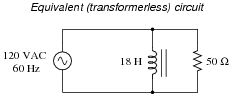
Also, draw an equivalent schematic diagram (with no transformer in it) illustrating the impedance ßeen" by the AC power source. Assume no winding resistance in either transformer winding, and a magnetic coupling coefficient between the two windings of exactly 1.
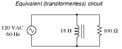
|
|
Follow-up question: what kind of impedance (predominantly resistive, inductive, or capacitive) does the AC source ßee" in this circuit? Contrast this against a situation with no load connected to the transformer at all.
Notes:
This question illustrates how reflected load impedance is ßeen" by the source, and how it interacts with the transformer's intrinsic winding impedance.
Question 18:
Calculate the primary winding current (magnitude and phase angle) for this resistively loaded transformer, with a primary inductance of 18 Henrys and a secondary inductance of 36 Henrys:
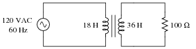
|
|
Also, draw an equivalent schematic diagram (with no transformer in it) illustrating the impedance ßeen" by the AC power source. Assume no winding resistance in either transformer winding, and a magnetic coupling coefficient between the two windings of exactly 1.
|
|
Follow-up question: what is the ßtep" ratio of this transformer, and is it step-up or step-down?
Notes:
This question illustrates how reflected load impedance is ßeen" by the source, and how it interacts with the transformer's intrinsic winding impedance.
Question 19:
An unloaded power transformer draws a primary current of 85 mA from its 240 volt, 60 Hz source. Neglecting any power losses, calculate the inductance of the primary winding. Also, calculate the inductance of the secondary winding given a step-down voltage ratio of 8:1.
Lprimary = Lsecondary =
Notes:
Ask your students to describe the mathematical relationship between winding turns ratio and inductance ratio.