Autotransformers
Question 1:
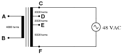
How much voltage is there between the following pairs of points in this circuit?
|
|
- �
- Between C and F: VCF =
- �
- Between A and B: VAB =
- �
- Between D and E: VDE =
- �
- Between D and F: VDF =
- �
- Between C and F: VCF = 48 V
- �
- Between A and B: VAB = 21.33 V
- �
- Between D and E: VDE = 10.67 V
- �
- Between D and F: VDF = 37.33 V
Notes:
This question checks students' ability to relate the winding ratios of a transformer to voltages in the circuit. The symbolism here is common in Europe, but not so common in the United States.
Question 2:
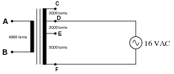
How much voltage is there between the following pairs of points in this circuit?
|
|
- �
- Between D and F: VDF =
- �
- Between A and B: VAB =
- �
- Between D and E: VDE =
- �
- Between C and F: VCF =
- �
- Between D and F: VDF = 16 V
- �
- Between A and B: VAB = 9.14 V
- �
- Between D and E: VDE = 4.57 V
- �
- Between C and F: VCF = 20.57 V
Notes:
This question checks students' ability to relate the winding ratios of a transformer to voltages in the circuit. Note that one of the voltages actually exceeds the source voltage of 16 volts, even though this is technically a ßtep-down" transformer. The fact that the source voltage is not impressed upon the entire primary winding is key here.
The symbolism for this transformer is common in Europe, but not so common in the United States.
Question 3:
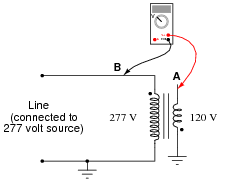
How much AC voltage is there between points A and B in this circuit?
|
|
Notes:
In reality, this is nothing more than an exercise in Kirchhoff's Voltage Law (KVL): determining the voltage between two points in a loop, knowing the voltages between other points in that same loop. Two principal challenges present themselves in this exercise: identifying the loop, and relating the dot convention to polarity markings. Different students will likely have different approaches to this problem, so it should make for an interesting discussion!
Question 4:
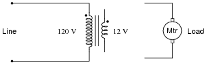
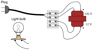
Connect the windings of this step-down transformer so that it "boosts" the voltage going to the load by 12 volts:
|
|
|
|
Notes:
Phase markings (the dots near the end of each winding) are very important when deciding which way to connect transformer windings! Some students may find it helpful to use DC polarity markings (+ and -) in addition to dots, to determine whether voltages will be in-phase (boosting) or out-of-phase (bucking).
Question 5:
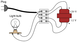
Connect the windings of this step-down transformer so that it "bucks" the voltage going to the light bulb by 12 volts:
|
|
|
|
Notes:
Phase markings (the dots near the end of each winding) are very important when deciding which way to connect transformer windings! Some students may find it helpful to use DC polarity markings (+ and -) in addition to dots, to determine whether voltages will be in-phase (boosting) or out-of-phase (bucking).
Question 6:
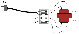
How could we possibly determine the phasing of the windings in this step-down transformer (120 VAC, 60 Hz primary) so we would know how to connect them for either boosting or bucking service?
|
|
Notes:
Note that the answer given to this question leaves the particular details of how to interpret the voltmeter readings unanswered. Challenge your students to figure this out on their own.
Given that autotransformer connections are so practical, it is important for students to know how to test a transformer to see how its (unmarked) windings are phased.
Question 7:
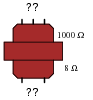
Suppose you had an audio impedance-matching transformer (1000 W to 8 W), and you wished to know the phase relationships of the windings. Unfortunately, the only test equipment you have is an analog DC voltmeter and a 9-volt battery. Explain how you would use these two devices to test winding "polarity."
|
|
Note: you may disregard the center-tap of the 1000 W primary winding.
Challenge question: calculate the turns ratio of this transformer, based on the ratio of impedances.
Notes:
Note that the answer given to this question leaves the particular details of how to interpret the voltmeter readings unanswered. Challenge your students to figure this out on their own.
Audio matching transformers are easy to obtain, so I encourage you have your students try this as a lab exercise.
Question 8:
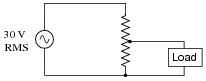
It should be obvious that the load voltage in this resistive voltage divider circuit will be less than 30 volts AC (RMS):
|
|
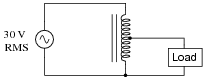
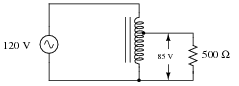
Likewise, it should be apparent that the load voltage in this inductive voltage divider circuit will be less than 30 volts AC (RMS):
|
|
From this brief analysis it would appear these two voltage divider circuits are equivalent to one another. However, there is a very important difference in terms of current: load versus supply. Estimate the load and source currents in each of these divider circuits, and comment on the difference(s) between the two.
Notes:
Ask your students to determine which voltage divider circuit will be more energy-efficient.
Question 9:
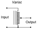
A popular piece of electrical bench test equipment is the Variac. Explain what a Variac is, how it works, and what applications it might be used for.
|
|
I'll let you research the answers to the other parts of this question!
Notes:
If you have a Variac in your lab, be sure to bring it to class for the discussion period so students may directly see what one looks like. If time permits, let your students experiment with it during discussion, to test their hypotheses about its function.
Question 10:
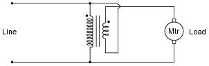
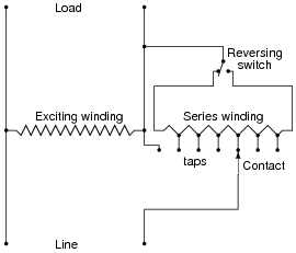
Devices called step regulators are sometimes used in electrical power distribution systems to boost or suppress line voltages, typically to a maximum of 10%:
|
|
The "Line" side of this autotransformer is the source of power, and the "Load" side connects to those devices consuming electrical power. The "Reversing switch" alters the transformer's function from boost to buck.
Determine which switch position is "boost" and which is "buck," and then determine which way the moving contact (the arrow symbol) needs to be moved in order to increase the voltage output, and to decrease the voltage output.
Incidentally, the zig-zag pattern of the windings is not standard for electronic schematic diagrams, though it is more common in electrical power system diagrams. I'll let you research how they draw resistors in these types of diagrams!
Notes:
The solution to this question may be easier for some to recognize if the regulator circuit is re-drawn using normal electronic schematic diagrams. Another tip is to simplify the schematic diagram by removing all the different tap positions, and draw the circuit using the full series winding.
It is important for students to realize that there are different types of electrical schematic diagrams. Power diagram symbolism is often confusing to people familiar with electronic schematic symbolism, and visa-versa.
Question 11:
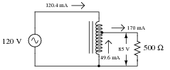
Calculate all currents in this autotransformer circuit, assuming perfect (100%) efficiency:
|
|
|
|
Follow-up question: based on these current figures, what economic advantage does an autotransformer have over a conventional transformer in terms of manufacturing cost?
Notes:
Discuss with your students the pro's and con's of autotransformers over regular transformers. Of course, there is the obvious disadvantage: loss of isolation between primary and secondary circuits. If this is not a problem, though, there are substantial advantages to be realized in using an autotransformer over a conventional transformer.
Question 12:
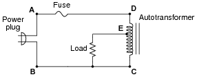
Suppose the load in this circuit suddenly stops receiving power:
|
|
Your first step in troubleshooting is to take some voltage measurements:
- �
- VAB = 120 V
- �
- VEC = 0 V
- �
- VDC = 120 V
Based on these measurements, where do you think the fault is in this circuit, and what type of fault is it?
Notes:
Ask your students to think of some other possibilities for failure in this circuit besides their first hypothesis. Also, discuss how you would verify (double-check) all hypotheses, with different meter measurements.