Basic circuit troubleshooting
Question 1:
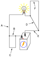
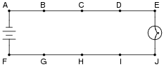
Determine if the light bulb will de-energize for each of the following breaks in the circuit. Consider just one break at a time:
|
|
- �
- Choose one option for each point:
- �
- A: de-energize / no effect
- �
- B: de-energize / no effect
- �
- C: de-energize / no effect
- �
- D: de-energize / no effect
- �
- E: de-energize / no effect
- �
- F: de-energize / no effect
- �
- A: de-energize
- �
- B: no effect
- �
- C: no effect
- �
- D: no effect
- �
- E: de-energize
- �
- F: no effect
Notes:
This question is an important one in the students' process of learning troubleshooting. Emphasize the importance of inductive thinking: deriving general principles from specific instances. What does the behavior of this circuit tell us about electrical continuity?
Question 2:
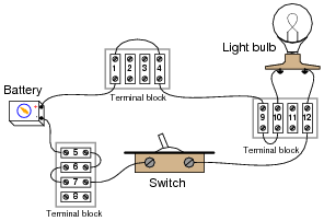
Examine the following illustration of a simple battery-switch-lamp circuit, connected together using screw-terminal blocks, each connection point on each terminal block identified by a unique number:
|
|
Determine whether or not voltage should be present between the following pairs of terminal block points with the switch in the ON position:
- �
- Points 1 and 5:
- �
- Points 6 and 7:
- �
- Points 4 and 10:
- �
- Points 9 and 12:
- �
- Points 6 and 12:
- �
- Points 9 and 10:
- �
- Points 4 and 7:
Now, determine whether or not voltage should be present between the following pairs of terminal block points with the switch in the OFF position:
- �
- Points 1 and 5:
- �
- Points 6 and 7:
- �
- Points 4 and 10:
- �
- Points 9 and 12:
- �
- Points 6 and 12:
- �
- Points 9 and 10:
- �
- Points 4 and 7:
- �
- Points 1 and 5: Voltage!
- �
- Points 6 and 7: No voltage
- �
- Points 4 and 10: No voltage
- �
- Points 9 and 12: Voltage!
- �
- Points 6 and 12: No voltage
- �
- Points 9 and 10: No voltage
- �
- Points 4 and 7: Voltage!
Switch OFF:
- �
- Points 1 and 5: Voltage!
- �
- Points 6 and 7: No voltage
- �
- Points 4 and 10: No voltage
- �
- Points 9 and 12: No voltage
- �
- Points 6 and 12: Voltage!
- �
- Points 9 and 10: No voltage
- �
- Points 4 and 7: Voltage!
Follow-up question: explain why there will be voltage or no voltage between each of these pairs of points for the two circuit conditions (switch on and switch off).
Notes:
This question is not really a troubleshooting question per se, but the principles involved in successfully determining the presence or absence of voltage are critically important to being able to troubleshoot simple circuits using a voltmeter.
I have found that the concept of electrically common points is most helpful when students first learn to relate voltage drop with continuity (breaks or non-breaks) in a circuit. You might want them to identify which points in this circuit are electrically common to one another (in either or both switch positions).
Question 3:
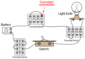
The following battery-switch-lamp circuit has a problem. Over time, corrosion has developed between the wire end and the screw terminal labeled "4" on the upper side of the top terminal block. This corroded connection now has a high resistance instead of a low resistance as it should. As a result, the light bulb does not energize when the switch is turned ON:
|
|
Taking voltage measurements with a voltmeter, how do you think this corrosion problem will reveal itself with the switch on the ON position? In other words, which voltage measurement in this circuit (i.e. between which pair or pairs of terminal block points) will be unusual as a result of the bad connection at point #4, and approximately how much voltage should that measurement be?
- �
- Points 1 and 4
- �
- Points 1 and 9
- �
- Points 1 and 10
Follow-up question: there are also several voltage measurements in this faulty circuit that will read abnormally low as a result of the corroded connection at point #4. Identify which pairs of points the abnormally low voltage will be measured between.
Notes:
Explain to your students what environmental factors contribute to corrosion (water, acids, caustics, etc.) and how a corroded electrical connection is usually not equivalent to a complete öpen" break in a circuit. Quite often a corroded connection is a substantial resistance of unstable value, leading to intermittent problems in the circuit.
Question 4:
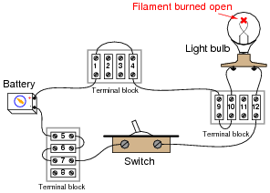
In this battery-switch-lamp circuit, the metal filament wire inside the lamp has burned up, so that it no longer forms an electrically continuous connection. In other words, the filament has failed öpen."
|
|
Of course, this means the lamp will not turn on, no matter what is done with the switch. It also means that most of the voltage measurements taken in the circuit will be the same as with a properly operating circuit. There is, however, one voltage measurement which will be different in the circuit with the burned-out filament than in a properly working circuit. Identify what pair or pairs of terminal block points this different voltage will be measured between, what switch state (ON or OFF) it will appear in, and what this different voltage measurement will actually be relative to the battery voltage.
Notes:
Be sure to ask your students why they think there will be no voltage dropped across the switch when it is OFF, now that the filament has burned open. It may be helpful to draw a schematic diagram (without all the terminal block points shown) as you discuss the reasoning with your students.
Question 5:
In this circuit, where would you expect to measure full battery voltage (between what pairs of test points)?
|
|
Notes:
This circuit provides an excellent opportunity to discuss the concept of ëlectrically common" points. Any points in a circuit directly connected together with wire are considered ëlectrically common" to each other: a voltage measurement referenced at any one of those points should be identical if referenced any of the other points as well.
Question 6:
In this circuit, where would you not expect to measure significant voltage (between what pairs of test points)?

|
|
Notes:
The answer uses a concept which I've found to be very helpful in understanding electrical circuits: the idea of points in a circuit being electrically common to each other. Simply put, this means the points are connected together by conductors of negligible resistance. Having nearly 0 ohms of resistance between points assures insignificant voltage drop, even for large currents.
Conversely, if significant voltage is measured between points in a circuit, you can be assured that those points are not electrically common to each other. Engage your students in a discussion of electrical commonality and expected voltage drops:
- �
- If voltage is measured between two points in a circuit, are those two points electrically common to each other? Why or why not?
- �
- If no voltage is measured between two points in a circuit, are those two points electrically common to each other? Why or why not?
Question 7:
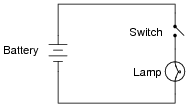
Suppose this battery and light bulb circuit failed to work. Using nothing but a voltmeter, how would you check the circuit to determine where the problem is located? Note: the letters indicate "test points" along the wiring where you may probe with the circuit with your voltmeter.

|
|
Notes:
A circuit like this is very easy to construct, and makes for an excellent classroom demonstration piece. I've used such a circuit, constructed on a piece of pegboard 2 feet by 4 feet, with metal screws acting as test points, for students to develop their troubleshooting skills in front of the class where everyone may observe and learn together.
It has been my experience that students who experience difficulty troubleshooting circuits in general usually experience difficulty troubleshooting this simple circuit in particular. Although the circuit itself couldn't be simpler, the fundamental concept of voltage as a quantity measurable only between 2 points is confusing for many. Spending lots of time learning to troubleshoot a circuit such as this will be greatly beneficial in the future!
Question 8:
Suppose this battery and light bulb circuit failed to work:

|
|
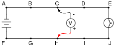
Using a voltmeter, a technician measures full battery voltage between the points C and H. What does this single measurement indicate about the condition of the circuit? Be as specific as you can.
Notes:
Some measurements given definite answers, while others only indefinite answers. In this particular question, the single voltage measurement tells us definite things about the left-hand side of the circuit, but little about the right-hand side. It is very important for students to develop the logical skill of distinguishing necessary conclusions from possible conclusions in troubleshooting scenarios. A skill like this takes time and practice to develop, so be sure to spend adequate time throughout the course with your students honing it!
Question 9:
Suppose this battery and light bulb circuit failed to work:

|
|
Using a voltmeter, a technician measures full battery voltage between the points C and H. The result of this single measurement indicates which half of the circuit there is a definite problem in. What would you recommend as the next voltmeter measurement to take in troubleshooting the circuit, following the same "divide in half" strategy?
Notes:
Some troubleshooters refer to this strategy as "divide and conquer," because it divides the possibilities of fault location by a factor of 2 with each step. Make sure your students understand that being able to immediately determine which part of a system is not faulted is a valuable time-saver.
Question 10:
Suppose this battery and light bulb circuit failed to work:

|
|
Using a voltmeter, a technician measures 0 volts between the points C and H. What does this single measurement indicate about the condition of the circuit? Be as specific as you can.
There may or may not be a problem on the right-hand side of the circuit, as well. Given this single voltage measurement, we simply cannot tell.
Notes:
There are times when a voltmeter indication of 0 volts is just as informative concerning a circuit fault as a non-zero measurement. In this case, the measurement tells us that a definite problem exists in one half of the circuit.
Question 11:
Suppose this battery and light bulb circuit failed to work:
|
|
Using a voltmeter, a technician measures 0 volts between the points C and H. The result of this single measurement indicates which half of the circuit there is a definite problem in. What would you recommend as the next voltmeter measurement to take in troubleshooting the circuit, following the same "divide in half" strategy?
Notes:
Some troubleshooters refer to this strategy as "divide and conquer," because it divides the possibilities of fault location by a factor of 2 with each step.
It is important to realize in situations such as this that no determination of faultlessness in the circuit has been made yet. By measuring 0 volts between points C and H, we know there is a definite problem in the left half of the circuit, but we have by no means "cleared" the right half of the circuit of any fault. For all we know, there may be faults in both halves of the circuit! Only further investigation will reveal the truth.
Question 12:
Suppose this battery and light bulb circuit failed to work:

|
|
Using nothing but a voltmeter, a technician measures voltage between the following sets of points:
- �
- Between A and C: 0 volts
- �
- Between D and G: 12 volts
- �
- Between E and J: 0 volts
- �
- Between B and E: 12 volts
Challenge question: identify which of the four measurement are unnecessary in determining the precise location of the fault in this circuit.
Challenge answer: the two "0 volt" measurements are unnecessary in determining the location of the fault in this circuit.
Notes:
Scenarios such as this are excellent for group discussion, encouraging students to think critically about the data and to apply their practical knowledge of electricity to a realistic problem.
Question 13:
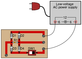
The circuit shown here is called a "bridge rectifier," and its purpose is to convert alternating current (from the "power-supply" unit) into direct current. Suppose you were instructed to check the continuity of the switch (SW1) mounted on the printed circuit board. What would be a fast and effective way of testing this switch's continuity (ideally, without removing the switch from the circuit board)?
|
|
Notes:
Challenge your students to think of other methods which could be used to check the switch's continuity. There is often more than one way to perform a certain check of component function, if you are knowledgeable in electrical theory and creative in your use of test equipment!
Question 14:
Identify which of these are true statements:
- 1.
- Between two points that are electrically common to each other, there is guaranteed to be zero voltage.
- 2.
- If zero voltage is measured between two points, those points must be electrically common to each other.
- 3.
- Between two points that are not electrically common to each other, there is guaranteed to be voltage.
- 4.
- If voltage is measured between two points, those points must not be electrically common to each other.
- 1.
- Between two points that are electrically common to each other, there is guaranteed to be zero voltage.
- 4.
- If voltage is measured between two points, those points must not be electrically common to each other.
For those having difficultly understanding this, test the following statements for truth. Each of these statements follows the same logical pattern of electrical statements given at the beginning of this question:
- 1.
- All rabbits are mammals.
- 2.
- All mammals are rabbits.
- 3.
- All non-rabbits are non-mammals.
- 4.
- All non-mammals are non-rabbits.
Notes:
What we have here is an exercise in Aristotelian logic. In either scenario (points in a circuit, or animals), statement 2 is the converse of statement 1, while statement 3 is the inverse and statement 4 is the contrapositive. Only the contrapositive of a statement is guaranteed to share the same truth value as the original statement.
This is no esoteric exercise. Rather, it is a hard-learned fact: many students mistakenly think that because there is guaranteed to be no voltage between electrically common points in a circuit, then the absence of voltage between two points must mean those two points are electrically common to each other! This is not necessarily true, because situations exist where two points may not be electrically common, yet still have no voltage between them. Electrical commonality is just one way that two points can have zero voltage between them, not the only way!
The contrapositive of this rule, however, is a valuable troubleshooting tool: if there is substantial voltage measured between two points in a circuit, then we know without a doubt that those two points are not electrically common to each other!
Question 15:
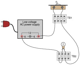
Suppose a technician were troubleshooting the following circuit, whose light bulb refused to light up:
|
|
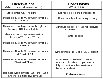
The technician records their steps on a piece of paper divided into two columns: Observations, and Conclusions, drawing a horizontal line underneath each conclusion after it is made:
|
|
Critique this technician's troubleshooting job, noting any errors or unnecessary steps.
The second conclusion ("Power supply is functioning properly") is understated. In actuality, the presence of voltage between these two points proves that not only is the power supply functioning properly, but both wires between the power supply and terminals TB1-1 and TB2-1 have good continuity, and the connections between the wires and their respective terminals are good as well. This eliminates several portions of the circuit as being problematic.
Checking for voltage across the light bulb terminals is a good step, but the lack of voltage does not prove the light bulb is not failed! All it means is that there is some other problem between the light bulb and the last two connections where voltage was measured (between TB1-1 and TB2-1). For all we know at this point, the light bulb could be failed as well as there being a failure somewhere else in the circuit.
Checking for voltage across the switch is another good step, but the lack of voltage there does not prove that the switch has good continuity, any more than a lack of voltage proved the light bulb's filament had good continuity either. There still could be multiple öpens" in this circuit.
The presence of voltage between TB2-1 and TB2-3 narrows the possibility of failure in the circuit quite a bit. Knowing that there is voltage between these two terminals proves there is good continuity from TB2-3 to TB1-3, through the switch, and all the way back to the power supply. From step 2 we already know there is good continuity from TB2-1 back to the power supply as well. This conclusively tells us that the problem(s) must lie between TB2-1 and TB2-3.
It is a wasted step to check for voltage between TB1-3 and TB2-1.
The measurement of voltage between TB2-1 and TB2-2 proves the location of the failure: an öpen" between those two points. It also proves that there are no other öpen" failures in the circuit.
The final step documenting replacement of the wire between TB2-1 and TB2-2, while not essential, is not really wasted, either. Troubleshooting journals such as this are helpful when searching for complex problems in large systems, where more than one person may have to work on finding the problem(s). If there is more than one failure in a system, it is helpful to document the repair for the benefit of anyone else working on solving the problem later!
Notes:
Circuit troubleshooting is the highest level of thinking required of many electrical and electronics professionals: to identify faults efficiently based on a knowledge of fundamental principles and test equipment usage. Good troubleshooters are rare, and in my opinion that has more to do with the lack of effective technical education than it does a lack of natural ability.
It is not enough to merely tell students what they should do in troubleshooting, or to give them easy-to-follow steps. Students must be placed in scenarios where they are required to think their way through to a solution. Fortunately, electrical circuit troubleshooting is an activity that works well for small groups of students to engage in as well as individual students. A "virtual" troubleshooting exercise such as this one is a good way to start students thinking in the right ways to becoming effective troubleshooters.
Question 16:
The following circuit has a problem. When the switch is closed, the lamp does not turn on:
|
|
Identify which of these hypothetical faults could account for this problem, and which could not account for the problem. In other words, which of these faults are possible, and which are not possible, given the symptoms exhibited by the circuit? Consider each of these hypothetical faults one at a time (no multiple, simultaneous faults):
- �
- Light bulb filament failed open
- �
- Switch failed shorted
- �
- Switch failed open
- �
- Light bulb filament failed open: Possible
- �
- Switch failed shorted: Not possible
- �
- Switch failed open: Possible
Follow-up question: if we allow ourselves to consider more than one fault occurring at the same time, does the ßwitch failed shorted" scenario become possible? Explain why or why not.
Notes:
This question helps students build the skill of eliminating unlikely fault possibilities, allowing them to concentrate instead on what is more likely. An important skill in system troubleshooting is the ability to formulate probabilities for various fault scenarios. Without this skill, you will waste a lot of time looking for unlikely faults, thereby wasting time.
For each fault scenario it is important to ask your students why they think it is possible or not possible. It might be that some students get the right answer(s) for the wrong reasons, so it is good to explore the reasoning for each answer.
Question 17:
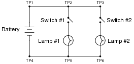
The following circuit has a problem. Switch #1 is able to control lamp #1, but lamp #2 never comes on no matter what is done with switch #2:
|
|
Identify which of these hypothetical faults could account for this problem, and which could not account for the problem. In other words, which of these faults are possible, and which are not possible, given the symptoms exhibited by the circuit? Consider each of these hypothetical faults one at a time (no multiple, simultaneous faults):
- �
- Battery is dead
- �
- Switch #2 failed open
- �
- Switch #2 failed shorted
- �
- Switch #1 failed open
- �
- Switch #1 failed shorted
- �
- Open wire between test points 1 and 2 (between TP1 and TP2)
- �
- Open wire between test points 5 and 6 (between TP5 and TP6)
- �
- Battery is dead: Not possible
- �
- Switch #2 failed open: Possible
- �
- Switch #2 failed shorted: Not possible
- �
- Switch #1 failed open: Not possible
- �
- Switch #1 failed shorted: Not possible
- �
- Open wire between test points 1 and 2 (between TP1 and TP2): Not possible
- �
- Open wire between test points 5 and 6 (between TP5 and TP6): Possible
Follow-up question: if we allow ourselves to consider more than one fault occurring at the same time, which of these scenarios becomes possible? Explain why.
Notes:
This question helps students build the skill of eliminating unlikely fault possibilities, allowing them to concentrate instead on what is more likely. An important skill in system troubleshooting is the ability to formulate probabilities for various fault scenarios. Without this skill, you will waste a lot of time looking for unlikely faults, thereby wasting time.
For each fault scenario it is important to ask your students why they think it is possible or not possible. It might be that some students get the right answer(s) for the wrong reasons, so it is good to explore the reasoning for each answer.
Question 18:
The following circuit has a problem. Switch #2 is able to control lamp #2, but lamp #1 never comes on no matter what is done with switch #1:

|
|
Identify which of these hypothetical faults could account for this problem, and which could not account for the problem. In other words, which of these faults are possible, and which are not possible, given the symptoms exhibited by the circuit? Consider each of these hypothetical faults one at a time (no multiple, simultaneous faults):
- �
- Battery is dead
- �
- Lamp #1 filament failed open
- �
- Lamp #2 filament failed open
- �
- Switch #2 failed open
- �
- Switch #2 failed shorted
- �
- Switch #1 failed open
- �
- Switch #1 failed shorted
- �
- Open wire between test points 1 and 2 (between TP1 and TP2)
- �
- Open wire between test points 4 and 5 (between TP4 and TP5)
- �
- Open wire between test points 5 and 6 (between TP5 and TP6)
- �
- Battery is dead: Not possible
- �
- Lamp #1 filament failed open: Possible
- �
- Lamp #2 filament failed open: Not possible
- �
- Switch #2 failed open: Not possible
- �
- Switch #2 failed shorted: Not possible
- �
- Switch #1 failed open: Possible
- �
- Switch #1 failed shorted: Not possible
- �
- Open wire between test points 1 and 2 (between TP1 and TP2): Not possible
- �
- Open wire between test points 4 and 5 (between TP4 and TP5): Not possible
- �
- Open wire between test points 5 and 6 (between TP5 and TP6): Not possible
Follow-up question: if we allow ourselves to consider more than one fault occurring at the same time, which of these scenarios becomes possible? Explain why.
Notes:
This question helps students build the skill of eliminating unlikely fault possibilities, allowing them to concentrate instead on what is more likely. An important skill in system troubleshooting is the ability to formulate probabilities for various fault scenarios. Without this skill, you will waste a lot of time looking for unlikely faults, thereby wasting time.
For each fault scenario it is important to ask your students why they think it is possible or not possible. It might be that some students get the right answer(s) for the wrong reasons, so it is good to explore the reasoning for each answer.