Basic troubleshooting strategies
Question 1:
A chandelier has five light bulbs in it, and one of them is not working. The problem could be in the chandelier's wiring (open wire connection, open connection in socket), or in the bulb itself (burned-out filament). Describe a procedure for determining the location of the problem (chandelier vs. bulb), without using any electrical test instruments.
Challenge question: can you think of a scenario where this troubleshooting procedure could cause additional failures in a system?
Notes:
This simple troubleshooting technique is applicable to a wide variety of electrical, electronic, and other types of systems: swap the suspect component with an identical component known to be functional, and see observe whether or not the problem changes location.
There is, however, a potential hazard to doing this. If the swapped component is indeed faulty, but in such a way that it causes a different part of the system to fail with connected to it, this technique will cause a failure in the system where the faulty component is moved to.
A similar hazard occurs if the swapped component was damaged because of other components in the system that it's connected to. In this case, the good component it it swapped with will be damaged in the swap, and the bad component will not work where it is moved to.
Question 2:
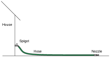
One day you decide to water your garden, using a garden hose that is already connected to a spigot on the side of your house:
|
|
When you turn on the valve at the spigot, though, no water comes out the nozzle at the other end of the hose. Explain the steps you would take to troubleshoot this problem.
- �
- Identify some probable sources of trouble in this garden hose ßystem."
- �
- Proceed in a logical manner to find the trouble as efficiently as possible.
Notes:
Discuss with your students both probable causes of this problem as well as strategies for locating the problem. Encourage students to analyze the system by dividing it into sections. Since garden hoses easily detach from spigots and nozzles alike, they lend themselves well to the so-called "divide-and-conquer" method of troubleshooting.
Question 3:
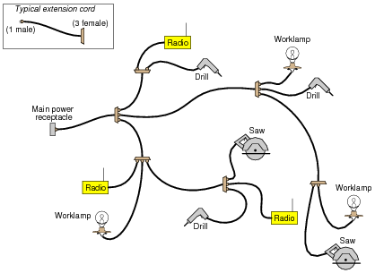
At a construction site, workers have used power extension cords to create a "network" of power cabling for their various electric tools. Each cord has one (male) plug and a receptacle (female) end that accepts up to three plugs:
|
|
Despite this dangerous wiring, all tools have functioned so far without trouble. Then suddenly both the worklight and the circular saw in the lower-right corner of the illustration stop working. All the other tools continue to function properly (including all the radios, which is very fortunate because the workers become irritable without their music).
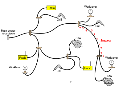
From this information alone, determine what sections of this "network" are good, and what sections are suspect.
|
|
Follow-up question: describe the general principle you used to locate the suspect area of this power network.
Notes:
Now, of course, it is possible that both the worklight and the saw suffered independent, simultaneous failures, and all the extension cords are good, but this is not very likely. Be sure to discuss this possibility with your students, and the reasoning why the one extension cord would be more likely to be faulted than two separate devices.
Question 4:
A new residential neighborhood is being built, and you are working as a member of the construction crew. One day, when the heating technicians are on-site doing checks of the gas furnaces in each new house, they report that the last house in the neighborhood does not have natural gas. The piping is installed, of course, but when they turn the gas valve on nothing comes out.
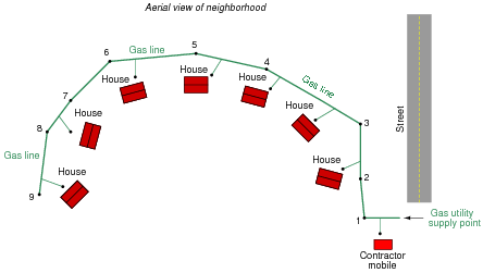
The gas pipeline servicing these houses is laid out in the following manner:
|
|
Each black dot on the diagram is a shutoff valve, used for isolating different sections of the service pipeline. Based on the heating technician's report, you conclude that the service pipeline going up to that house must not be "live," and that one of the numbered valves was probably left in the off position. But which one could it be?
You know that the main utility connection at the street is "live," because the gas heater in the contractor mobile building is working just fine. You decide to go to valve #8 and check for gas pressure at that point in the pipeline with a portable pressure gauge, then checking the pressure at each valve location down the pipeline until you find where there is good gas pressure. However, before you step out of the room to go do this, one of your co-workers suggests you start your search at the middle point of the pipeline instead: at the location of valve #4.
Explain why your co-worker's idea is better, and also what your next step would be if: (a) you did find pressure at that point, and (b) if you did not find pressure at that point.
Notes:
This problem gives students a chance to explore the "divide and conquer" strategy of troubleshooting in a context that is very simple and does not require knowledge of electricity.
Question 5:
As a technician, you are sent to troubleshoot a complex piece of electronic equipment that has stopped working. Upon opening the cabinet door for this equipment, your nose is greeted by the pungent odor of burnt circuit board (a smell you are unlikely to forget, once having experienced it). What does this simple fact indicate (or possibly indicate) about the nature of the equipment's fault?
Follow-up question: upon further investigation, you locate the charred remains of an electronic component, located on one of the system's circuit boards. Is this the only fault, being that it is the only component visibly damaged? Explain why or why not.
Notes:
It is important for students to understand that not all faults become visible, even if catastrophic!
Be sure to discuss with your students that the burnt component may very well be a victim of another component failure, and not the cause of the system fault. For instance, shorted wiring located far from the equipment enclosure may have caused the components to destruct. This is a common assumption made by beginning troubleshooters: that the most obvious failure is the only failure, or that it must be the primary failure.
Question 6:
Two computer technicians are called to troubleshoot malfunctioning computer systems. Although the symptoms in each system are very similar, the histories of the two systems are not. The first computer is a unit that has been in operation for over two years, while the second system is a brand-new prototype, still in the developmental stages.
Without knowing any more details on these two computer systems, what recommendations can you give to the two technicians about to troubleshoot them? If you were asked to troubleshoot each system, how would you approach the two systems differently? What ranges of problems might you expect from each system?
Notes:
As an illustration of this principle, you might want to elaborate on your own experiences as an electronics instructor. When assisting students with lab projects, what typical problems do you encounter with the circuits they build, and how do these problems typically differ from problems you've seen in real-life electronic equipment?
Question 7:
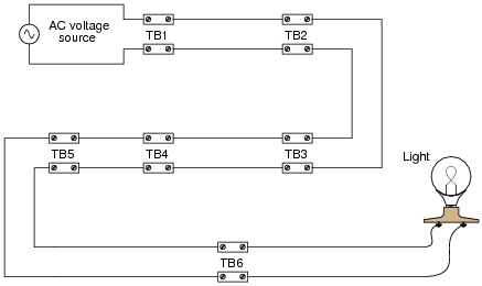
An electrician is troubleshooting a faulty light circuit, where the power source and light bulb are far removed from one another:
|
|
As you can see in the diagram, there are several terminal blocks ("TB") through which electrical power is routed to the light bulb. These terminal blocks provide convenient connection points to join wires together, enabling sections of wire to be removed and replaced if necessary, without removing and replacing all the wiring.
The electrician is using a voltmeter to check for the presence of voltage between pairs of terminals in the circuit. The terminal blocks are located too far apart to allow for voltage checks between blocks (say, between one connection in TB2 and another connection in TB3). The voltmeter's test leads are only long enough to check for voltage between pairs of connections at each terminal block.
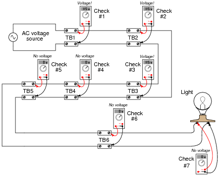
In the next diagram, you can see the electrician's voltage checks, in the sequence that they were taken:
|
|
Based on the voltage indications shown, can you determine the location of the circuit fault? What about the electrician's choice of steps - do you think the voltage measurements taken were performed in the most efficient sequence, or would you recommend a different order to save time?
- �
- The distance between terminal blocks.
- �
- The time required to gain access for a voltage check, upon reaching the terminal block location.
Follow-up question: describe a scenario where the given sequence of voltage readings would be the most efficient. Describe another scenario where a different sequence of voltage readings could have saved time in locating the problem.
Notes:
One of the most common troubleshooting techniques taught to technicians is the so-called "divide and conquer" method, whereby the system or signal path is divided into halves with each measurement, until the location of the fault is pinpointed. However, there are some situations where it might actually save time to perform measurements in a linear progression (from one end to the other, until the power or signal is lost). Efficient troubleshooters never limit themselves to a rigid methodology if other methods are more efficient.
Question 8:
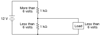
This circuit is called a voltage divider, because it presents a fractional portion of the total voltage to the load:
|
|
(Of course, with no load connected, the voltage across the lower resistor would be precisely 6 volts. With the load connected, the parallel combination of load and 1 kW resistor results in an effective resistance of less than 1 kW on the lower half of the divider, resulting in a voltage of less than half the total supply voltage.)
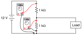
Suppose that something goes wrong in this voltage divider circuit, and the load voltage suddenly falls to zero. A technician following the "divide-and-conquer" troubleshooting strategy begins by measuring voltage across the lower resistor (finding 0 volts), then measuring voltage across both resistors (finding 12 volts):
|
|
Based on these measurements, the technician concludes that the upper resistor must be failed open. Upon disassembling the divider circuit and checking resistance with an ohmmeter, though, both resistors are revealed to be in perfect operating condition.
What error did the technician make in concluding the upper resistor must have been failed open? Where do you think the problem is in this circuit?
Notes:
This is a common mistake students make when applying the "divide-and-conquer" method of troubleshooting: that whatever component(s) located between the point of good measurement and the point of bad measurement must be the source of the problem. While this simple reasoning may apply in finding öpen" faults in long lengths of wire, it does not necessarily hold true for more complex circuits, as other faults may result in similar effects.
Question 9:
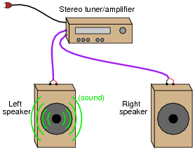
This stereo system has a problem: only one of the two speakers is emitting sound. While the left speaker seems to be working just fine, the right speaker is silent regardless of where any of the stereo's controls are set:
|
|
Identify three possible faults that could cause this problem to occur, and identify what components of the stereo system are known to be okay (be sure to count each cable as a separate component of the system!).
- Possible faults in the system:
- �
- Fault #1:
- �
- Fault #2:
- �
- Fault #3:
- Components known to be okay in the system:
- �
- Component #1:
- �
- Component #2:
- �
- Component #3:
Explain how you might go about troubleshooting this problem, using no test equipment whatsoever. Remember that the speaker cables detach easily from the speakers and from the amplifier.
Possible faults include the right speaker, the right speaker cable, and the right output channel of the amplifier. A very good way to determine which of these components is faulted is to swap cables and speakers between sides, but I'll let you determine which component swaps test which components.
Notes:
Swapping components can be a very powerful means of troubleshooting system problems where interchangeable components exist.
Question 10:
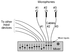
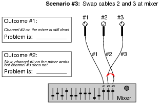
A music recording studio is equipped with three microphones, each of which connect to the "mixer" panel by means of shielded cables:
|
|
The purpose of the mixer is to function as a multi-channel audio signal amplifier, to control the volume of each sound channel so that a good "mix" is obtained for recording. The studio engineer will use the individual controls on the mixer to "blend" the inputs for the best recording tone and quality.
This system has a problem, though. Microphone #2 seems to be "dead," meaning that channel #2 on the mixer does not register any signal when the singer sings into that microphone. All the other channels are working just fine, though.
Being the studio technician, you job is to troubleshoot this problem in the shortest time possible. Unfortunately, in your rush to get to the job site you forgot to bring your test equipment. That isn't a problem, however, because you know how to troubleshoot systems by swapping interchangeable components.
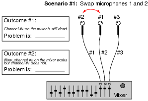
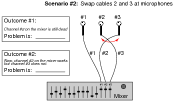
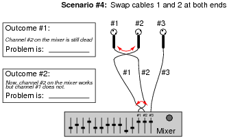
I will present four different ßwap" scenarios to you, with two different outcomes for each. Your task is to declare what is known about the location of the fault based on these scenarios and outcomes.
|
|
|
|
|
|
|
|
Scenario #2, outcome #2: microphone #2 is faulty.
Scenario #2, outcome #1: problem is not in the microphone.
Scenario #2, outcome #2: microphone #2 is faulty.
Scenario #3, outcome #1: mixer input #2 is faulty.
Scenario #3, outcome #2: the problem is not in the mixer.
Scenario #4, outcome #1: the problem is not in the cable.
Scenario #4, outcome #2: cable #2 is faulty.
Notes:
Your more adept students will immediately recognize that scenarios 1 and 2 are really quite the same. The logical thinking behind this troubleshooting strategy may confound some of your students, so be prepared to spend adequate time covering and re-covering (if necessary) this question. By the way, this type of question is excellent for a written test!
Question 11:
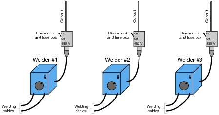
At a construction site, several electric ärc" welders are plugged into 480 volt receptacles. Each receptacle has its own safety disconnect switch and fuse overcurrent protection:
|
|
You, as an electronics technician working at the job site, happen to be walking past these welders when one of the welding personnel stops you to ask for help.
"You're an electrician, right?"
"Not exactly," you reply, "but maybe I can help you anyway."
"My welder's dead - it doesn't even turn on. Can you check it out?"
You didn't bring your multimeter or any other test equipment, so you can't check for voltage at the receptacle. As you look around the job site, you notice that no one is using welder #2. When you flip it's power switch on, welder #2 turns on just like it should. Deciding to apply your ßwap interchangeable components" troubleshooting strategy, you turn off both welders' power switches, then turn off the disconnect switches at both receptacles and swap the power cables between receptacles:

|
|
When you turn the disconnect switches on and try to start both welders, you find that neither one turns on now! Switching the power cables back to their original receptacles doesn't make things better, either. Both welders #1 and #2 are still "dead," which is a worse situation than what you first encountered. This is not good, because the person who called you for help is beginning to cast angry looks in your direction, and you are fairly sure the operator of welder #2 won't be much happier when he returns to find his welder non-functional as well.
Identify the most likely location of the fault in this system, and explain why the ßwap interchangeable components" strategy got you into trouble.
Notes:
This situation is very realistic, and underscores the need for careful thinking on the part of the troubleshooter when deciding what specific troubleshooting strategy to apply. Despite the undeniable power of the ßwap interchangeable components" strategy, it is not fool-proof.
Question 12:
A friend of yours brings you their damaged stereo amplifier, hoping that perhaps you would be able to repair it cheaper than the local electronics repair shop. The amplifier was damaged at a recent party, when one of your friend's guests turned up the volume to full and left it there until smoke billowed out of the power amplifier chassis.
Your friend has already done some troubleshooting of his own: after turning off the amplifier and letting the smoke clear, he turned it back on at low volume to find that the left channel is dead, but the right channel is still working. He then swapped speakers and speaker wires, and consistently found that whatever speaker was plugged into the left channel did not make sound, but the speaker plugged into the right channel always did.
You remove the chassis cover on the amplifier and look inside. There, the damage is visually apparent: both of the power transistors for the left channel output are burnt beyond recognition. You unsolder the transistors from the circuit board and unscrew them from the heat sink, but you cannot read the part numbers on their cases due to the thermal damage. This is not good, because without knowing the proper part numbers, your friend cannot order the proper replacement transistors to repair the amplifier.
As usual, there is no schematic diagram supplied with this amplifier that would indicate the proper part numbers. What do you do?
Notes:
Some students may question this logic, believing that the left and right channels of a stereo amplifier would be mirror-symmetric rather than identical, and thus possibly contain different components. You may answer this objection by appealing to the indistinguishable sound of the two channels, when listened to separately (mono). There is nothing "right-handed" or "left-handed" about the two channels. Each one is identical to the other at the circuit level, because each channel is expected to perform exactly the same.
Question 13:
A very powerful method for discerning cause-and-effect relationships is scientific method. One commonly accepted algorithm (series of steps) for scientific method is the following:
- 1.
- Observation
- 2.
- Formulate an hypothesis (an educated guess)
- 3.
- Predict a unique consequence of that hypothesis
- 4.
- Test the prediction by experiment
- 5.
- If test fails, go back to step #2. If test passes, hypothesis is provisionally confirmed.
This methodology is also very useful in technical troubleshooting, since troubleshooting is fundamentally a determination of cause for an observed effect. Read the following description of an experienced troubleshooter diagnosing an mechanical noise problem in a bicycle, and match the troubleshooter's steps to those five steps previously described for scientific method:
- One day a bicyclist called a mechanic friend of his over the telephone, and describes a problem with his bicycle. The bicycle is making a rhythmic "clicking" sound as it is pedaled, but the bicyclist is not very mechanically inclined, and cannot determine the cause of the noise.
The mechanic considered some of the options. Being a rhythmic noise, it was probably being caused by one of the bicycle's rotating objects. This includes the wheels, crank, and chain, which all rotate at different speeds. After a bit of thought, the mechanic asked his bicyclist friend a question.
"Does the pace of the clicking increase as you ride faster?" The bicyclist answered, "Yes, it does."
"If you shift into a higher gear so that your crank is turning slower for the same road speed, does the pace of the clicking change?" asked the mechanic. The bicyclist admitted he didn't know the answer to this question, as he hadn't thought to pay attention to this detail. After riding the bike once again to test the mechanic's idea, the bicyclist reported back. "No, the pace of the clicking does not change when I shift gears. It only changes with changes in road speed."
Upon hearing this, the mechanic knew the general location of the problem, and continued his troubleshooting over the telephone with further questions for the bicyclist.
Notes:
Discuss with your students the relationship between the mechanic's steps and the steps given for scientific method. Have them locate the observation, hypothesis, prediction, and test.
Once students have successfully identified the mechanic's reasoning, ask them to explain how the prediction of noise rhythm distinguishes which part of the bicycle is making the noise.
Also, discuss whether this concludes the diagnostic procedures, or if there is more troubleshooting left to do. What steps are recommended to take next, if any?
Question 14:
A very powerful method for discerning cause-and-effect relationships is scientific method. One commonly accepted algorithm (series of steps) for scientific method is the following:
- 1.
- Observation
- 2.
- Formulate an hypothesis (an educated guess)
- 3.
- Predict a unique consequence of that hypothesis
- 4.
- Test the prediction by experiment
- 5.
- If test fails, go back to step #2. If test passes, hypothesis is provisionally confirmed.
This methodology is also very useful in technical troubleshooting, since troubleshooting is fundamentally a determination of cause for an observed effect. Read the following description of an experienced troubleshooter diagnosing an automotive electrical problem, and match the troubleshooter's steps to those five steps previously described for scientific method:
- One day a car owner approached a mechanic friend of theirs with a problem. The battery in this car seemed to be dying, requiring frequent jump-starts from other vehicles, or the application of a battery charger overnight, to be able to start reliably. "What could be the problem?" asked the car owner to the mechanic.
The mechanic considered some of the options. One possibility was that a parasitic load was draining the battery of its charge when the car was shut off. Another possibility was that the car's charging system (the engine-driven generator and its associated circuitry) was faulty and not charging the battery when the engine was running. A third possibility was that the battery itself was defective, and unable to hold a charge.
"Let's check the battery voltage with the engine stopped, and with the engine running," said the mechanic. The two walked over to the car and opened the hood, then the mechanic connected a voltmeter to the battery's terminals. It read 11.3 volts DC. This was a 12-volt (nominal) battery.
"Start the car," said the mechanic, still watching the voltmeter. As the electric starting motor labored to turn the engine, the voltmeter's reading sagged to 9 volts. Once the engine started and the electric starter disengaged, the voltmeter rebounded to 11.2 volts.
"That's the problem!" shouted the mechanic. With that, the owner stopped the car's engine.
- One day a car owner approached a mechanic friend of theirs with a problem. The battery in this car seemed to be dying, requiring frequent jump-starts from other vehicles, or the application of a battery charger overnight, to be able to start reliably.1 "What could be the problem?" asked the car owner to the mechanic.
The mechanic considered some of the probable causes. One possibility was that a parasitic load was draining the battery of its charge when the car was shut off.2 Another possibility was that the car's charging system (the engine-drive generator and its associated circuitry) was faulty and not charging the battery when the engine was running.2 A third possibility was that the battery itself was defective, and unable to hold a charge.2
"Let's check the battery voltage with the engine stopped, and with the engine running," said the mechanic.(3) The two walked over to the car and opened the hood, then the mechanic connected a voltmeter to the battery's terminals. It read 11.3 volts DC. This was a 12-volt (nominal) battery.
"Start the car," said the mechanic, still watching the voltmeter. As the electric starting motor labored to turn the engine, the voltmeter's reading sagged to 9 volts. Once the engine started and the electric starter disengaged, the voltmeter rebounded to 11.2 volts.4
"That's the problem!" shouted the mechanic.(5) With that, the owner stopped the car's engine.
Notes:
Once students have successfully identified the mechanic's reasoning, ask them to explain how the prediction of battery voltage uniquely relates to only one of the three hypotheses stated.
Also, discuss whether this concludes the diagnostic procedures, or if there is more troubleshooting left to do. What steps are recommended to take next, if any?
Question 15:
Troubleshooting a system of any kind requires scientific thinking: sound deductive reasoning from effect to cause, and cause to effect. One of the principles frequently applied in science is Ockham's Razor, named after Sir William of Ockham (1284-1350). In Ockham's own words, the principle is as follows:
|
Applied to troubleshooting electric circuits, one could re-phrase Ockham's Razor as such:
|
Justify the use of Ockham's Razor in troubleshooting circuits. Why should we first consider single faults to account for the problems the circuit is having rather than considering interesting combinations of faults which would account for the same problems?
Notes:
A mistake common to new students is to consider wild combinations of faults in a broken system before thoroughly considering all the simpler possibilities. This seems especially true when students answer troubleshooting questions on written exams. When actually working on real circuits, students seem more likely to first look for simple causes.