BJT amplifier troubleshooting
Question 1:
As an instructor of electronics, I am called upon frequently to help students troubleshoot their malfunctioning lab circuits. When I approach a student's self-built circuit to troubleshoot it, though, I often begin the process with a very different mindset than if I were troubleshooting a malfunctioning circuit on a real job site.
Aside from different safety considerations and a very different work environment, what else do you think I might consider differently when approaching a student-built circuit? Specifically, how might the range of probable faults differ between a professionally-installed electronic system that malfunctions and a student's lab project that malfunctions? What generalizations might you make about this difference in troubleshooting perspective, regarding the construction and operational history of the circuit in question?
Notes:
Although sound troubleshooting technique will ultimately yield a solution, asking "pre-diagnostic" questions such as this will greatly enhance your efficiency as a troubleshooter. Discuss this with your students, enlightening them if possible with anecdotes from your own troubleshooting experiences.
Question 2:
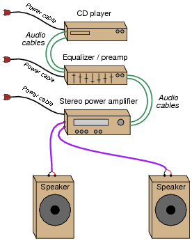
Examine the following "component" stereo system closely:
|
|
The CD player generates the audio signal to be amplified, while the equalizer/preamp modifies the tone of the signal to suit the listener's preferences and the power amplifier provides adequate power to drive the speakers.
Suppose this system has a problem: no sound at all coming out of either speaker. All components in the system are turned on, as indicated by power lights on the front panels. All control knobs seem to be set to their proper positions, as well. The CD player indicates the disk is being played, and that it is presently playing a song. Despite all these good indicators, though, no sound is heard from the speakers.
Being prepared at all times to troubleshoot electronic systems, you have a digital multimeter close by which you may use to check for the presence of audio signals (set the meter to measure AC millivolts). All audio signal cables (including the speaker cables) may be unplugged to provide access for your meter's test probes.
At what point in the system would you begin testing for the presence of an audio signal? Explain why you chose that point, and describe your subsequent actions based on the results of that test.
Notes:
Discuss with your students how this is an ideal application for the "divide-and-conquer" strategy of troubleshooting, where you divide the signal path into halves, checking for the presence of a signal at each half-way point, narrowing in on the location of the faulted component in a rapid manner.
Question 3:
Here are a few good steps to take prior to applying any specific troubleshooting strategies to a malfunctioning amplifier circuit:
- �
- Measure the output signal with an oscilloscope.
- �
- Determine if the amplifier is receiving a good input signal.
- �
- Check to see that the amplifier is receiving good-quality power.
Explain why taking these simple steps may save a lot of time in the troubleshooting process. For example, why bother checking the amplifier's output signal if you already know it isn't outputting what it's supposed to? What, exactly, constitutes "good-quality" power for an amplifier circuit?
The rationale for checking the input signal should be easy to understand. I'll let you answer this one!
"Good-quality" power consists of DC within the proper voltage range of the amplifier circuit, with negligible ripple voltage.
Follow-up question #1: suppose you discover that the "faulty" amplifier is in fact not receiving any input signal at all? Does this test exonerate the amplifier itself? How would might you simulate a proper input signal for the amplifier, for the purposes of testing it?
Follow-up question #2: explain how to measure power supply ripple voltage, using only a digital multimeter. How would you measure ripple using an oscilloscope?
Notes:
In my own experience I have found these steps to be valuable time-savers prior to beginning any formal troubleshooting process. In general terms, check for output, check for input, and check for power.
New technicians are often surprised at how often complex problems may be caused by something as simple as "dirty" power. Since it only takes a few moments to check, and can lead to a wide range of problems, it is not wasted effort.
Question 4:
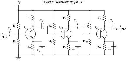
The three-stage amplifier shown here has a problem. Despite being supplied with good, "clean" DC power and an adequate input signal to amplify, there is no output signal whatsoever:
|
|
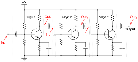
Explain how you would use the "divide and conquer" or "divide by two" strategy of troubleshooting to locate the amplification stage where the fault is. (This is where you divide the signal path into different sections, then test for good signal at points along that path so as to narrow the problem down to one-half of the circuit, then to one-quarter of the circuit, etc.)
Show the lines of demarcation where you would divide the circuit into distinct sections, and identify input and output test points for each of those sections.
|
|
Challenge question: how well do you suppose this same troubleshooting strategy would work to locate the fault within a particular amplification stage?
Notes:
Multi-stage amplifier circuits lend themselves well to the "divide and conquer" strategy of troubleshooting, especially when the stages are as symmetrical as these.
Question 5:
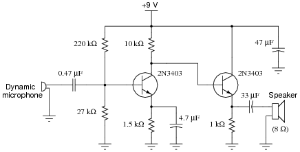
In order to successfully troubleshoot any electronic circuit to the component level, one must have a good understanding of each component's function within the context of that circuit. Transistor amplifiers are no exception to this rule. The following schematic shows a simple, two-stage audio amplifier circuit:
|
|
Identify the role of the following components in this audio amplifier circuit:
- �
- The 0.47 mF capacitor connected to the microphone
- �
- The 220 k W and 27 k W resistor pair
- �
- The 4.7 mF electrolytic capacitor connected across the 1.5 k W resistor
- �
- The 33 mF electrolytic capacitor connected to the speaker
- �
- The 47 mF electrolytic capacitor connected to the power supply rail
Additionally, answer the following questions concerning the circuit's design:
- �
- What configuration is each stage (common-base, common-collector, common-emitter)?
- �
- Why not just use one transistor stage to drive the speaker? Why is an additional stage necessary?
- �
- What might happen if the 47 mF "decoupling" capacitor were not in the circuit?
- �
- Why does the second stage of the amplifier not need its own voltage divider to set bias voltage as the first stage does?
- �
- The 0.47 mF capacitor connected to the microphone: passes (AC) audio signal, blocks DC bias voltage from reaching microphone
- �
- The 220 k W and 27 k W resistor pair: sets DC bias voltage for first transistor stage
- �
- The 4.7 mF electrolytic capacitor connected across the 1.5 k W resistor: bypasses (AC) audio signal around emitter resistor, for maximum AC voltage gain
- �
- The 33 mF electrolytic capacitor connected to the speaker: couples (AC) audio signal to speaker while blocking DC bias voltage from speaker
- �
- The 47 mF electrolytic capacitor connected to the power supply rail: "decouples" any AC signal from the power supply, by providing a low-impedance (short) path to ground
The question regarding the necessity of the 47 mF decoupling capacitor is tricky to answer, so I'll elaborate a bit here. Power supply decoupling is a good design practice, because it can ward off a wide range of problems. AC "ripple" voltage should never be present on the power supply "rail" conductors, as transistor circuits function best with pure DC power. The purpose of a decoupling capacitor is to subdue any ripple, whatever its source, by acting as a low-impedance ßhort" to ground for AC while not presenting any loading to the DC power.
Although it may not seem possible at first inspection, the lack of a decoupling capacitor in this audio amplifier circuit can actually lead to self-oscillation (where the amplifier becomes a tone generator) under certain power supply and load conditions! If the power supply is poorly regulated and/or poorly filtered, the presence of a decoupling capacitor will greatly diminish line-frequency "hum" noise heard in the speaker.
For the rest of the questions, I'll let you figure out answers on your own!
Notes:
Incidentally, this circuit makes a good ïntercom" amplifier for a student project. Using a small dynamic speaker for the microphone, and another speaker (or audio headset) on the receiving end of a long cable connected to the amplifier output, students can easily talk between two rooms in a building, or even between buildings.
Question 6:
Often times, component failures in transistor circuits will cause significant shifting of DC (quiescent) parameters. This is a benefit for the troubleshooter, as it means many faults may be located simply by measuring DC voltages (with no signal input) and comparing those voltages against what is expected. The most difficult part, though, is determining what DC voltage levels to expect at various points in an amplifier circuit.
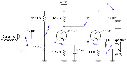
Examine this two-stage audio amplifier circuit, and estimate the DC voltages at all the points marked by bold letters and arrows (A through G), with reference to ground. Assume that conducting PN junctions will drop 0.7 volts, that loading effects on the voltage divider are negligible, and that the transistor's collector and emitter currents are virtually the same magnitude:
|
|
VA �
VB �
VC �
VD �
VE �
VF �
VG �
VB � 0.98 volts
VC � 0.28 volts
VD � 7.1 volts
VE � 6.4 volts
VF = 0 volts (precisely)
VG = 9 volts (precisely)
Follow-up question: explain why voltages VA, VF, and VG can be precisely known, while all the other DC voltages in this circuit are approximate. Why is this helpful to know when troubleshooting a faulted amplifier circuit?
Notes:
The calculations used to estimate these values are quite simple, and should prove no trouble for students to derive who have a basic knowledge of DC circuit calculations (voltage dividers, series voltage drops, etc.).
Question 7:
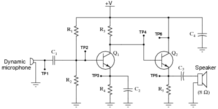
Study this audio amplifier circuit closely:
|
|
Then, determine whether the DC voltage at each test point (VTP1 through VTP6) with respect to ground will increase, decrease, or remain the same for each of the given fault conditions:
-
Fault VTP1 VTP2 VTP3 VTP4 VTP5 VTP6
R1 failed open Same Same
R2 failed open Same Same
R3 failed open Same Same
R4 failed open Same Same
R5 failed open Same Same
Short between TP2 and ground Same Same
C2 failed shorted Same Same
Q1 collector failed open Same Same
When analyzing component faults, consider only one fault at a time. That is, for each row in the table, you should analyze the circuit as though the only fault in it is the one listed in the far left column of that row.
-
Fault VTP1 VTP2 VTP3 VTP4 VTP5 VTP6
R1 failed open Same 0 0 � � Same
R2 failed open Same � � � � Same
R3 failed open Same � � � � Same
R4 failed open Same Same � � � Same
R5 failed open Same � Same � Same � � Same
Short between TP2 and ground Same 0 0 � � Same
C2 failed shorted Same � 0 � � Same
Q1 collector failed open Same � � � � Same
Follow-up question: why don't test point voltages VTP1 or VTP6 ever change?
Notes:
I was able to verify specific voltages by building this circuit and faulting each component as described. Although I was not always able to predict the magnitude of the change, I could always predict the direction. This is really all that should be expected of beginning students.
The really important aspect of this question is for students to understand why the test point voltages change as they do. Discuss each fault with your students, and how one can predict the effects just by looking at the circuit.
Question 8:
The likelihood that a given component will fail in the öpen" mode is quite often not the same as the likelihood that it will fail ßhorted." Based on the research you do and your own personal experience with troubleshooting electronic circuits, determine whether the following components are more likely to fail open or fail shorted (this includes partial, or high-resistance, shorts):
- �
- Resistors:
- �
- Capacitors:
- �
- Inductors:
- �
- Transformers:
- �
- Bipolar transistors:
I encourage you to research information on these devices' failure modes, as well as glean from your own experiences building and troubleshooting electronic circuits.
- �
- Resistors: open
- �
- Capacitors: shorted
- �
- Inductors: open or short equally probable
- �
- Transformers: open or short equally probable
- �
- Bipolar transistors: shorted
Follow-up question: When bipolar transistors fail shorted, the short is usually apparent between the collector and emitter terminals (although sometimes all three terminals may register shorted, as though the transistor were nothing more than a junction between three wires). Why do you suppose this is? What is it about the base terminal that makes it less likely to "fuse" with the other terminals?
Notes:
Emphasize to your students how a good understanding of common failure modes is important to efficient troubleshooting technique. Knowing which way a particular component is more likely to fail under normal operating conditions enables the troubleshooter to make better judgments when assessing the most probable cause of a system failure.
Of course, proper troubleshooting technique should always reveal the source of trouble, whether or not the troubleshooter has any experience with the failure modes of particular devices. However, possessing a detailed knowledge of failure probabilities allows one to check the most likely sources of trouble first, which generally leads to faster repairs.
An organization known as the Reliability Analysis Center, or RAC, publishes detailed analyses of failure modes for a wide variety of components, electronic as well as non-electronic. They may be contacted at 201 Mill Street, Rome, New York, 13440-6916. Data for this question was gleaned from the RAC's publication, Part Failure Mode Distributions.
Question 9:
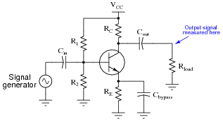
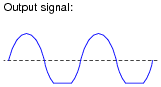
Suppose you were troubleshooting the following amplifier circuit, and found the output signal to be "clipped" on the negative peaks:
|
|
|
|
If you knew that this amplifier was a new design, and might not have all its components properly sized, what type of problem would you suspect in the circuit? Please be as specific as possible.
Notes:
Discuss with your students how to determine whether the bias voltage is too great or too small, based on the observed output waveform. It isn't difficult to do so long as students understand why biasing exists and how it works.
Question 10:
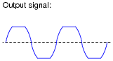
Suppose you were troubleshooting the following amplifier circuit, and found the output signal to be symmetrically "clipped" on both the positive and negative peaks:

|
|
|
|
If you knew that this amplifier was a new design, and might not have all its components properly sized, what type of problem would you suspect in the circuit? Please be as specific as possible.
Of course, changing either of these resistor values will alter the bias ("Q") point of the amplifier, which may necessitate subsequent changes in the value of either R1 or R2!
Notes:
Discuss with your students how to determine the necessary changes in resistor values, based on the determination that the gain is excessive. This is actually very easy to do just by examining the gain formula for a common-emitter amplifier.
Another option to consider here is the addition of a negative feedback signal path to tame the amplifier's gain. This modification would have the added benefit of improving circuit linearity.
Question 11:
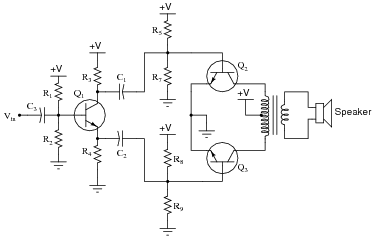
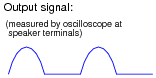
This class-B audio power amplifier circuit has a problem: its output is very distorted, resembling half of a sine wave when tested with an input signal from a function generator:
|
|
|
|
List some of the possible faults in this system, based on the output signal shown by the oscilloscope. Also, determine which components, if any, are known to be good based on the same data:
- Possible faults in the system:
- �
- Fault #1:
- �
- Fault #2:
- �
- Fault #3:
- Components known to be okay in the system:
- �
- Component #1:
- �
- Component #2:
- �
- Component #3:
- Possible faults in the system:
- �
- Fault #1: Transistor Q2 or Q3 failed open
- �
- Fault #2: Resistor R5 or R8 failed open
- �
- Fault #3: Half of transformer primary winding failed open
- Components known to be okay in the system:
- �
- Component #1: Secondary winding of transformer
- �
- Component #2: Resistor R4
- �
- Component #3: Input coupling capacitor C3
Follow-up question #1: suppose that after testing this amplifier on your workbench with a "dummy" load (8 W resistor connected to the speaker terminals), you happened to notice that transistor Q2 was slightly warm to the touch, while transistor Q3 was still at room temperature. What would this extra information indicate about the amplifier's problem?
Follow-up question #2: describe the potential safety hazards involved with touching a power transistor in an operating circuit. If you wished to compare the operating temperature of these two transistors, how could you safely do it?
Notes:
The symmetry inherent in push-pull amplifiers makes troubleshooting easier in some respects. As always, though, component-level troubleshooting requires a detailed understanding of component function within the context of the specific circuit being diagnosed. No matter how ßimple" the circuit may be, a student will be helpless to troubleshoot it down to the component level unless they understand how and why each component functions.
Giving the clue regarding transistor temperature is important for two reasons. First, it provides more data for students to use in confirming fault possibilities. Second, it underscores the importance of non-electrical data. Efficient troubleshooters make (safe) use of all available data when investigating a problem, and that often requires creative thinking.