Inductive reactance
Question 1:
| Don't just sit there! Build something!! |
Learning to mathematically analyze circuits requires much study and practice. Typically, students practice by working through lots of sample problems and checking their answers against those provided by the textbook or the instructor. While this is good, there is a much better way.
You will learn much more by actually building and analyzing real circuits, letting your test equipment provide the änswers" instead of a book or another person. For successful circuit-building exercises, follow these steps:
- 1.
- Carefully measure and record all component values prior to circuit construction.
- 2.
- Draw the schematic diagram for the circuit to be analyzed.
- 3.
- Carefully build this circuit on a breadboard or other convenient medium.
- 4.
- Check the accuracy of the circuit's construction, following each wire to each connection point, and verifying these elements one-by-one on the diagram.
- 5.
- Mathematically analyze the circuit, solving for all voltage and current values.
- 6.
- Carefully measure all voltages and currents, to verify the accuracy of your analysis.
- 7.
- If there are any substantial errors (greater than a few percent), carefully check your circuit's construction against the diagram, then carefully re-calculate the values and re-measure.
For AC circuits where inductive and capacitive reactances (impedances) are a significant element in the calculations, I recommend high quality (high-Q) inductors and capacitors, and powering your circuit with low frequency voltage (power-line frequency works well) to minimize parasitic effects. If you are on a restricted budget, I have found that inexpensive electronic musical keyboards serve well as "function generators" for producing a wide range of audio-frequency AC signals. Be sure to choose a keyboard "voice" that closely mimics a sine wave (the "panflute" voice is typically good), if sinusoidal waveforms are an important assumption in your calculations.
As usual, avoid very high and very low resistor values, to avoid measurement errors caused by meter "loading". I recommend resistor values between 1 kW and 100 kW.
One way you can save time and reduce the possibility of error is to begin with a very simple circuit and incrementally add components to increase its complexity after each analysis, rather than building a whole new circuit for each practice problem. Another time-saving technique is to re-use the same components in a variety of different circuit configurations. This way, you won't have to measure any component's value more than once.
Notes:
It has been my experience that students require much practice with circuit analysis to become proficient. To this end, instructors usually provide their students with lots of practice problems to work through, and provide answers for students to check their work against. While this approach makes students proficient in circuit theory, it fails to fully educate them.
Students don't just need mathematical practice. They also need real, hands-on practice building circuits and using test equipment. So, I suggest the following alternative approach: students should build their own "practice problems" with real components, and try to mathematically predict the various voltage and current values. This way, the mathematical theory "comes alive," and students gain practical proficiency they wouldn't gain merely by solving equations.
Another reason for following this method of practice is to teach students scientific method: the process of testing a hypothesis (in this case, mathematical predictions) by performing a real experiment. Students will also develop real troubleshooting skills as they occasionally make circuit construction errors.
Spend a few moments of time with your class to review some of the "rules" for building circuits before they begin. Discuss these issues with your students in the same Socratic manner you would normally discuss the worksheet questions, rather than simply telling them what they should and should not do. I never cease to be amazed at how poorly students grasp instructions when presented in a typical lecture (instructor monologue) format!
An excellent way to introduce students to the mathematical analysis of real circuits is to have them first determine component values (L and C) from measurements of AC voltage and current. The simplest circuit, of course, is a single component connected to a power source! Not only will this teach students how to set up AC circuits properly and safely, but it will also teach them how to measure capacitance and inductance without specialized test equipment.
A note on reactive components: use high-quality capacitors and inductors, and try to use low frequencies for the power supply. Small step-down power transformers work well for inductors (at least two inductors in one package!), so long as the voltage applied to any transformer winding is less than that transformer's rated voltage for that winding (in order to avoid saturation of the core).
A note to those instructors who may complain about the "wasted" time required to have students build real circuits instead of just mathematically analyzing theoretical circuits:
What is the purpose of students taking your course?
If your students will be working with real circuits, then they should learn on real circuits whenever possible. If your goal is to educate theoretical physicists, then stick with abstract analysis, by all means! But most of us plan for our students to do something in the real world with the education we give them. The "wasted" time spent building real circuits will pay huge dividends when it comes time for them to apply their knowledge to practical problems.
Furthermore, having students build their own practice problems teaches them how to perform primary research, thus empowering them to continue their electrical/electronics education autonomously.
In most sciences, realistic experiments are much more difficult and expensive to set up than electrical circuits. Nuclear physics, biology, geology, and chemistry professors would just love to be able to have their students apply advanced mathematics to real experiments posing no safety hazard and costing less than a textbook. They can't, but you can. Exploit the convenience inherent to your science, and get those students of yours practicing their math on lots of real circuits!
Question 2:
Suppose someone were to ask you to differentiate electrical reactance (X) from electrical resistance (R). How would you distinguish these two similar concepts from one another, using your own words?
Notes:
This is an excellent point of crossover with your students' studies in elementary physics, if they are studying physics now or have studied physics in the past. The energy-storing actions of inductors and capacitors are quite analogous to the energy-storing actions of masses and springs (respectively, if you associate velocity with current and force with voltage). In the same vein, resistance is analogous to kinetic friction between a moving object and a stationary surface. The parallels are so accurate, in fact, that the electrical properties of R, L, and C have been exploited to model mechanical systems of friction, mass, and resilience in circuits known as analog computers.
Question 3:
As a general rule, inductors oppose change in (choose: voltage or current), and they do so by . . . (complete the sentence).
Based on this rule, determine how an inductor would react to a constant AC current that increases in frequency. Would an inductor drop more or less voltage, given a greater frequency? Explain your answer.
An inductor will drop a greater amount of AC voltage, given the same AC current, at a greater frequency.
Notes:
This question is an exercise in qualitative thinking: relating rates of change to other variables, without the use of numerical quantities. The general rule stated here is very, very important for students to master, and be able to apply to a variety of circumstances. If they learn nothing about inductors except for this rule, they will be able to grasp the function of a great many inductor circuits.
Question 4:
|
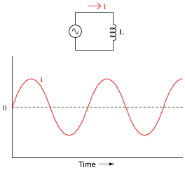
We know that the formula relating instantaneous voltage and current in an inductor is this:
|
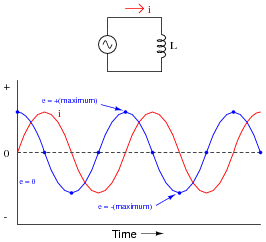
Knowing this, determine at what points on this sine wave plot for inductor current is the inductor voltage equal to zero, and where the voltage is at its positive and negative peaks. Then, connect these points to draw the waveform for inductor voltage:
|
|
How much phase shift (in degrees) is there between the voltage and current waveforms? Which waveform is leading and which waveform is lagging?
|
|
For an inductor, voltage is leading and current is lagging, by a phase shift of 90o.
Notes:
This question is an excellent application of the calculus concept of the derivative: relating one function (instantaneous voltage, e) with the instantaneous rate-of-change of another function (current, [di/dt]).
Question 5:
Does an inductor's opposition to alternating current increase or decrease as the frequency of that current increases? Also, explain why we refer to this opposition of AC current in an inductor as reactance instead of resistance.
Notes:
Ask your students to define the relationship between inductor reactance and frequency as either "directly proportional" or ïnversely proportional". These are two phrases used often in science and engineering to describe whether one quantity increases or decreases as another quantity increases. Your students definitely need to be familiar with both these phrases, and be able to interpret and use them in their technical discussions.
Also, discuss the meaning of the word "non-dissipative" in this context. How could we prove that the opposition to current expressed by an inductor is non-dissipative? What would be the ultimate test of this?
Question 6:
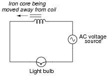
What will happen to the brightness of the light bulb as the iron core is moved away from the wire coil in this circuit? Explain why this happens.
|
|
Follow-up question: what circuit failure(s) could cause the light bulb to glow brighter than it should?
Notes:
One direction you might want to lead your students in with this question is how AC power may be controlled using this principle. Controlling AC power with a variable reactance has a definite advantage over controlling AC power with a variable resistance: less wasted energy in the form of heat.
Question 7:
An inductor rated at 4 Henrys is subjected to a sinusoidal AC voltage of 24 volts RMS, at a frequency of 60 hertz. Write the formula for calculating inductive reactance (XL), and solve for current through the inductor.
|
The current through this inductor is 15.92 mA RMS.
Notes:
I have consistently found that qualitative (greater than, less than, or equal) analysis is much more difficult for students to perform than quantitative (punch the numbers on a calculator) analysis. Yet, I have consistently found on the job that people lacking qualitative skills make more ßilly" quantitative errors because they cannot validate their calculations by estimation.
In light of this, I always challenge my students to qualitatively analyze formulae when they are first introduced to them. Ask your students to identify what will happen to one term of an equation if another term were to either increase, or decrease (you choose the direction of change). Use up and down arrow symbols if necessary to communicate these changes graphically. Your students will greatly benefit in their conceptual understanding of applied mathematics from this kind of practice!
Question 8:
At what frequency does a 350 mH inductor have 4.7 kW of reactance? Write the formula for solving this, in addition to calculating the frequency.
Notes:
Be sure to ask your students to demonstrate the algebraic manipulation of the original formula, in providing the answer to this question. Algebraic manipulation of equations is a very important skill to have, and it comes only by study and practice.
Question 9:
How much inductance would an inductor have to possess in order to provide 540 W of reactance at a frequency of 400 Hz? Write the formula for solving this, in addition to calculating the frequency.
Notes:
Be sure to ask your students to demonstrate the algebraic manipulation of the original formula, in providing the answer to this question. Algebraic manipulation of equations is a very important skill to have, and it comes only by study and practice.
Question 10:
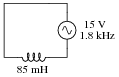
Explain all the steps necessary to calculate the amount of current in this inductive AC circuit:
|
|
Notes:
The current is not difficult to calculate, so obviously the most important aspect of this question is not the math. Rather, it is the procedure of calculation: what to do first, second, third, etc., in obtaining the final answer.
Question 11:
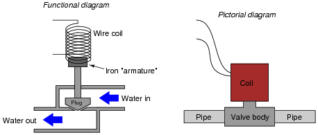
A solenoid valve is a mechanical shutoff device actuated by electricity. An electromagnet coil produces an attractive force on an iron ärmature" which then either opens or closes a valve mechanism to control the flow of some fluid. Shown here are two different types of illustrations, both showing a solenoid valve:
|
|
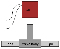
Some solenoid valves are constructed in such a way that the coil assembly may be removed from the valve body, separating these two pieces so that maintenance work may be done on one without interfering with the other. Of course, this means the valve mechanism will no longer be actuated by the magnetic field, but at least one piece may be worked upon without having to remove the other piece from whatever it may be connected to:
|
|
This is commonly done when replacement of the valve mechanism is needed. First, the coil is lifted off the valve mechanism, then the maintenance technician is free to remove the valve body from the pipes and replace it with a new valve body. Lastly, the coil is re-installed on the new valve body and the solenoid is once more ready for service, all without having to electrically disconnect the coil from its power source.
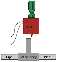
However, if this is done while the coil is energized, it will overheat and burn up in just a few minutes. To prevent this from happening, the maintenance technicians have learned to insert a steel screwdriver through the center hole of the coil while it is removed from the valve body, like this:
|
|
With the steel screwdriver shank taking the place of the iron armature inside the valve body, the coil will not overheat and burn up even if continually powered. Explain the nature of the problem (why the coil tends to burn up when separated from the valve body) and also why a screwdriver put in place of the iron armature works to prevent this from happening.
Notes:
When I first saw this practice in action, I almost fell over laughing. It is both practical and ingenious, as well as being an excellent example of variable inductance (and inductive reactance) arising from varying reluctance.
Question 12:
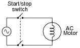
When AC power is initially applied to an electric motor (before the motor shaft has an opportunity to start moving), the motor äppears" to the AC power source to be a large inductor:
|
|
If the voltage of the 60 Hz AC power source is 480 volts RMS, and the motor initially draws 75 amps RMS when the double-pole single-throw switch closes, how much inductance (L) must the motor windings have? Ignore any wire resistance, and assume the motor's only opposition to current in a locked-rotor condition is inductive reactance (XL).
Notes:
In reality, motor winding resistance plays a substantial part in this sort of calculation, but I simplified things a bit just to give students a practical context for their introductory knowledge of inductive reactance.
Question 13:
In analyzing circuits with inductors, we often take the luxury of assuming the constituent inductors to be perfect; i.e., purely inductive, with no ßtray" properties such as winding resistance or inter-winding capacitance.
Real life is not so generous. With real inductors, we have to consider these factors. One measure often used to express the "purity" of an inductor is its so-called Q rating, or quality factor.
Write the formula for calculating the quality factor (Q) of a coil, and describe some of the operational parameters that may affect this number.
|
Notes:
Your students should be able to immediately understand that Q is not a static property of an inductor. Let them explain what makes Q vary, based on their knowledge of inductive reactance.