Impedance
Question 1:
| Don't just sit there! Build something!! |
Learning to mathematically analyze circuits requires much study and practice. Typically, students practice by working through lots of sample problems and checking their answers against those provided by the textbook or the instructor. While this is good, there is a much better way.
You will learn much more by actually building and analyzing real circuits, letting your test equipment provide the änswers" instead of a book or another person. For successful circuit-building exercises, follow these steps:
- 1.
- Carefully measure and record all component values prior to circuit construction.
- 2.
- Draw the schematic diagram for the circuit to be analyzed.
- 3.
- Carefully build this circuit on a breadboard or other convenient medium.
- 4.
- Check the accuracy of the circuit's construction, following each wire to each connection point, and verifying these elements one-by-one on the diagram.
- 5.
- Mathematically analyze the circuit, solving for all voltage and current values.
- 6.
- Carefully measure all voltages and currents, to verify the accuracy of your analysis.
- 7.
- If there are any substantial errors (greater than a few percent), carefully check your circuit's construction against the diagram, then carefully re-calculate the values and re-measure.
For AC circuits where inductive and capacitive reactances (impedances) are a significant element in the calculations, I recommend high quality (high-Q) inductors and capacitors, and powering your circuit with low frequency voltage (power-line frequency works well) to minimize parasitic effects. If you are on a restricted budget, I have found that inexpensive electronic musical keyboards serve well as "function generators" for producing a wide range of audio-frequency AC signals. Be sure to choose a keyboard "voice" that closely mimics a sine wave (the "panflute" voice is typically good), if sinusoidal waveforms are an important assumption in your calculations.
As usual, avoid very high and very low resistor values, to avoid measurement errors caused by meter "loading". I recommend resistor values between 1 kW and 100 kW.
One way you can save time and reduce the possibility of error is to begin with a very simple circuit and incrementally add components to increase its complexity after each analysis, rather than building a whole new circuit for each practice problem. Another time-saving technique is to re-use the same components in a variety of different circuit configurations. This way, you won't have to measure any component's value more than once.
Notes:
It has been my experience that students require much practice with circuit analysis to become proficient. To this end, instructors usually provide their students with lots of practice problems to work through, and provide answers for students to check their work against. While this approach makes students proficient in circuit theory, it fails to fully educate them.
Students don't just need mathematical practice. They also need real, hands-on practice building circuits and using test equipment. So, I suggest the following alternative approach: students should build their own "practice problems" with real components, and try to mathematically predict the various voltage and current values. This way, the mathematical theory "comes alive," and students gain practical proficiency they wouldn't gain merely by solving equations.
Another reason for following this method of practice is to teach students scientific method: the process of testing a hypothesis (in this case, mathematical predictions) by performing a real experiment. Students will also develop real troubleshooting skills as they occasionally make circuit construction errors.
Spend a few moments of time with your class to review some of the "rules" for building circuits before they begin. Discuss these issues with your students in the same Socratic manner you would normally discuss the worksheet questions, rather than simply telling them what they should and should not do. I never cease to be amazed at how poorly students grasp instructions when presented in a typical lecture (instructor monologue) format!
An excellent way to introduce students to the mathematical analysis of real circuits is to have them first determine component values (L and C) from measurements of AC voltage and current. The simplest circuit, of course, is a single component connected to a power source! Not only will this teach students how to set up AC circuits properly and safely, but it will also teach them how to measure capacitance and inductance without specialized test equipment.
A note on reactive components: use high-quality capacitors and inductors, and try to use low frequencies for the power supply. Small step-down power transformers work well for inductors (at least two inductors in one package!), so long as the voltage applied to any transformer winding is less than that transformer's rated voltage for that winding (in order to avoid saturation of the core).
A note to those instructors who may complain about the "wasted" time required to have students build real circuits instead of just mathematically analyzing theoretical circuits:
What is the purpose of students taking your course?
If your students will be working with real circuits, then they should learn on real circuits whenever possible. If your goal is to educate theoretical physicists, then stick with abstract analysis, by all means! But most of us plan for our students to do something in the real world with the education we give them. The "wasted" time spent building real circuits will pay huge dividends when it comes time for them to apply their knowledge to practical problems.
Furthermore, having students build their own practice problems teaches them how to perform primary research, thus empowering them to continue their electrical/electronics education autonomously.
In most sciences, realistic experiments are much more difficult and expensive to set up than electrical circuits. Nuclear physics, biology, geology, and chemistry professors would just love to be able to have their students apply advanced mathematics to real experiments posing no safety hazard and costing less than a textbook. They can't, but you can. Exploit the convenience inherent to your science, and get those students of yours practicing their math on lots of real circuits!
Question 2:
In DC circuits, we have Ohm's Law to relate voltage, current, and resistance together:
|
In AC circuits, we similarly need a formula to relate voltage, current, and impedance together. Write three equations, one solving for each of these three variables: a set of Ohm's Law formulae for AC circuits. Be prepared to show how you may use algebra to manipulate one of these equations into the other two forms.
|
|
|
If using phasor quantities (complex numbers) for voltage, current, and impedance, the proper way to write these equations is as follows:
|
|
|
Bold-faced type is a common way of denoting vector quantities in mathematics.
Notes:
Although the use of phasor quantities for voltage, current, and impedance in the AC form of Ohm's Law yields certain distinct advantages over scalar calculations, this does not mean one cannot use scalar quantities. Often it is appropriate to express an AC voltage, current, or impedance as a simple scalar number.
Question 3:
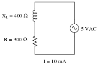
In this AC circuit, the resistor offers 300 W of resistance, and the inductor offers 400 W of reactance. Together, their series opposition to alternating current results in a current of 10 mA from the 5 volt source:
|
|
How many ohms of opposition does the series combination of resistor and inductor offer? What name do we give to this quantity, and how do we symbolize it, being that it is composed of both resistance (R) and reactance (X)?
Follow-up question: suppose that the inductor suffers a failure in its wire winding, causing it to öpen." Explain what effect this would have on circuit current and voltage drops.
Notes:
Students may experience difficulty arriving at the same quantity for impedance shown in the answer. If this is the case, help them problem-solve by suggesting they simplify the problem: short past one of the load components and calculate the new circuit current. Soon they will understand the relationship between total circuit opposition and total circuit current, and be able to apply this concept to the original problem.
Ask your students why the quantities of 300 W and 400 W do not add up to 700 W like they would if they were both resistors. Does this scenario remind them of another mathematical problem where 3 + 4 = 5? Where have we seen this before, especially in the context of electric circuits?
Once your students make the cognitive connection to trigonometry, ask them the significance of these numbers' addition. Is it enough that we say a component has an opposition to AC of 400 W, or is there more to this quantity than a single, scalar value? What type of number would be suitable for representing such a quantity, and how might it be written?
Question 4:
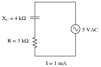
In this AC circuit, the resistor offers 3 kW of resistance, and the capacitor offers 4 kW of reactance. Together, their series opposition to alternating current results in a current of 1 mA from the 5 volt source:
|
|
How many ohms of opposition does the series combination of resistor and capacitor offer? What name do we give to this quantity, and how do we symbolize it, being that it is composed of both resistance (R) and reactance (X)?
Notes:
Students may experience difficulty arriving at the same quantity for impedance shown in the answer. If this is the case, help them problem-solve by suggesting they simplify the problem: short past one of the load components and calculate the new circuit current. Soon they will understand the relationship between total circuit opposition and total circuit current, and be able to apply this concept to the original problem.
Ask your students why the quantities of 3 kW and 4 kW do not add up to 7 kW like they would if they were both resistors. Does this scenario remind them of another mathematical problem where 3 + 4 = 5? Where have we seen this before, especially in the context of electric circuits?
Once your students make the cognitive connection to trigonometry, ask them the significance of these numbers' addition. Is it enough that we say a component has an opposition to AC of 4 kW, or is there more to this quantity than a single, scalar value? What type of number would be suitable for representing such a quantity, and how might it be written?
Question 5:
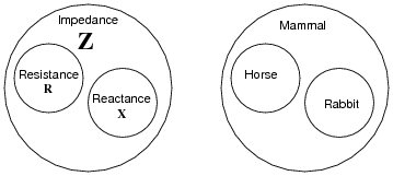
While studying DC circuit theory, you learned that resistance was an expression of a component's opposition to electric current. Then, when studying AC circuit theory, you learned that reactance was another type of opposition to current. Now, a third term is introduced: impedance. Like resistance and reactance, impedance is also a form of opposition to electric current.
Explain the difference between these three quantities (resistance, reactance, and impedance) using your own words.
|
|
Resistance is a type of impedance, and so is reactance. The difference between the two has to do with energy exchange.
Notes:
The given answer is far from complete. I've shown the semantic relationship between the terms resistance, reactance, and impedance, but I have only hinted at the conceptual distinctions between them. Be sure to discuss with your students what the fundamental difference is between resistance and reactance, in terms of electrical energy exchange.
Question 6:
It is often necessary to represent AC circuit quantities as complex numbers rather than as scalar numbers, because both magnitude and phase angle are necessary to consider in certain calculations.
When representing AC voltages and currents in polar form, the angle given refers to the phase shift between the given voltage or current, and a "reference" voltage or current at the same frequency somewhere else in the circuit. So, a voltage of 3.5 V �-45o means a voltage of 3.5 volts magnitude, phase-shifted 45 degrees behind (lagging) the reference voltage (or current), which is defined to be at an angle of 0 degrees.
But what about impedance (Z)? Does impedance have a phase angle, too, or is it a simple scalar number like resistance or reactance?
Calculate the amount of current that would go through a 100 mH inductor with 36 volts RMS applied to it at a frequency of 400 Hz. Then, based on Ohm's Law for AC circuits and what you know of the phase relationship between voltage and current for an inductor, calculate the impedance of this inductor in polar form. Does a definite angle emerge from this calculation for the inductor's impedance? Explain why or why not.
Notes:
This is a challenging question, because it asks the student to defend the application of phase angles to a type of quantity that does not really possess a wave-shape like AC voltages and currents do. Conceptually, this is difficult to grasp. However, the answer is quite clear through the Ohm's Law calculation (Z = E/I).
Although it is natural to assign a phase angle of 0o to the 36 volt supply, making it the reference waveform, this is not actually necessary. Work through this calculation with your students, assuming different angles for the voltage in each instance. You should find that the impedance computes to be the same exact quantity every time.
Question 7:
Express the impedance (Z) in both polar and rectangular forms for each of the following components:
- �
- A resistor with 500 W of resistance
- �
- An inductor with 1.2 kW of reactance
- �
- A capacitor with 950 W of reactance
- �
- A resistor with 22 kW of resistance
- �
- A capacitor with 50 kW of reactance
- �
- An inductor with 133 W of reactance
- �
- A resistor with 500 W of resistance: 500 W � 0o or 500 + j0 W
- �
- An inductor with 1.2 kW of reactance: 1.2 kW � 90o or 0 + j1.2k W
- �
- A capacitor with 950 W of reactance: 950 W � -90o or 0 - j950 W
- �
- A resistor with 22 kW of resistance: 22 kW � 0o or 22k + j0 W
- �
- A capacitor with 50 kW of reactance: 50 kW � -90o or 0 - j50k W
- �
- An inductor with 133 W of reactance: 133 W � 90o or 0 + j133 W
Follow-up question: what would the phasors look like for resistive, inductive, and capacitive impedances?
Notes:
In your discussion with students, emphasize the consistent nature of phase angles for impedances of "pure" components.
Question 8:
Real inductors and capacitors are never purely reactive. There will inevitably be some resistance intrinsic to these devices as well.
Suppose an inductor has 57 W of winding resistance, and 1500 W of reactance at a particular frequency. How would this combination be expressed as a single impedance? State your answer in both polar and rectangular forms.
Notes:
Mention to your students that "real" components such as this may be modeled in a diagram as a combination of two "pure" components, in this case a resistor and an inductor. Discuss with them the benefits of "modeling" component characteristics in this manner, since it is a very common practice in engineering.
This is a very important concept to understand: that reactive components are never purely reactive. Parasitic resistance is impossible to avoid short of using superconductors. Even then, inductors are bound to have some parasitic capacitance, and capacitors are bound to have some parasitic inductance!
Question 9:
Not only do reactive components unavoidably possess some parasitic (ßtray") resistance, but they also exhibit parasitic reactance of the opposite kind. For instance, inductors are bound to have a small amount of capacitance built-in, and capacitors are bound to have a small amount of inductance built-in. These effects are not intentional, but they exist anyway.
Describe how a small amount of capacitance comes to exist within an inductor, and how a small amount of inductance comes to exist within a capacitor. Explain what it is about the construction of these two reactive components that allows the existence of öpposite" characteristics.
Notes:
Once students have identified the mechanisms of parasitic reactances, challenge them with inventing means of minimizing these effects. This is an especially practical exercise for understanding parasitic inductance in capacitors, which is very undesirable in decoupling capacitors used to stabilize power supply voltages near integrated circuit "chips" on printed circuit boards. Fortunately, most of the stray inductance in a decoupling capacitor is due to how it's mounted to the board, rather than anything within the structure of the capacitor itself.
Question 10:
Suppose you were given a component and told it was either a resistor, an inductor, or a capacitor. The component is unmarked, and impossible to visually identify. Explain what steps you would take to electrically identify what type of component it was, and what its value was, without the use of any test equipment except a signal generator, a multimeter (capable of measuring nothing but voltage, current, and resistance), and some miscellaneous passive components (resistors, capacitors, inductors, switches, etc.). Demonstrate your technique if possible.
Notes:
This is an excellent opportunity to brainstorm as a group and experiment on real components. There is obviously more than one way to make the determinations of identity and value! Use the class time to engage your students in lively discussion and debate over how to approach this practical problem.
Question 11:
Suppose you were given two components and told one was an inductor while the other was a capacitor. Both components are unmarked, and impossible to visually distinguish or identify. Explain how you could use an ohmmeter to distinguish one from the other, based on each component's response to direct current (DC).
Then, explain how you could approximately measure the value of each component using nothing more than a sine-wave signal generator and an AC meter capable only of precise AC voltage and current measurements across a wide frequency range (no direct capacitance or inductance measurement capability), and show how the reactance equation for each component (L and C) would be used in your calculations.
Challenge question: suppose the only test equipment you had available was a 6-volt battery and an old analog volt-milliammeter (with no resistance check function). How could you use this primitive gear to identify which component was the inductor and which was the capacitor?
Notes:
This is an excellent opportunity to brainstorm as a group and experiment on real components. The purpose of this question is to make the reactance equations more "real" to students by having them apply the equations to a realistic scenario. The ohmmeter test is based on DC component response, which may be thought of in terms of reactance at a frequency at or near zero. The multimeter/generator test is based on AC response, and will require algebraic manipulation to convert the canonical forms of these equations to versions appropriate for calculating L and C.
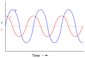
Question 12:
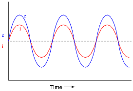
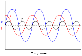
If a sinusoidal voltage is applied to an impedance with a phase angle of 0o, the resulting voltage and current waveforms will look like this:
|
|
Given that power is the product of voltage and current (p = i e), plot the waveform for power in this circuit.
|
|
Notes:
Ask your students to observe the waveform shown in the answer closely, and determine what sign the power values always are. Note how the voltage and current waveforms alternate between positive and negative, but power does not. Of what significance is this to us? What does this indicate about the nature of a load with an impedance phase angle of 0o?
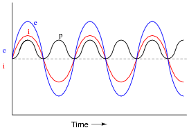
Question 13:
If a sinusoidal voltage is applied to an impedance with a phase angle of 90o, the resulting voltage and current waveforms will look like this:
|
|
Given that power is the product of voltage and current (p = i e), plot the waveform for power in this circuit. Also, explain how the mnemonic phrase ËLI the ICE man" applies to these waveforms.
|
|
The mnemonic phrase, ËLI the ICE man" indicates that this phase shift is due to an inductance rather than a capacitance.
Notes:
Ask your students to observe the waveform shown in the answer closely, and determine what sign the power values are. Note how the power waveform alternates between positive and negative values, just as the voltage and current waveforms do. Ask your students to explain what negative power could possibly mean.
Of what significance is this to us? What does this indicate about the nature of a load with an impedance phase angle of 90o?
The phrase, ËLI the ICE man" has been used be generations of technicians to remember the phase relationships between voltage and current for inductors and capacitors, respectively. One area of trouble I've noted with students, though, is being able to interpret which waveform is leading and which one is lagging, from a time-domain plot such as this.
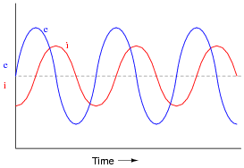
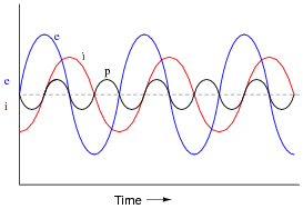
Question 14:
If a sinusoidal voltage is applied to an impedance with a phase angle of -90o, the resulting voltage and current waveforms will look like this:
|
|
Given that power is the product of voltage and current (p = i e), plot the waveform for power in this circuit. Also, explain how the mnemonic phrase ËLI the ICE man" applies to these waveforms.
|
|
The mnemonic phrase, ËLI the ICE man" indicates that this phase shift is due to a capacitance rather than an inductance.
Notes:
Ask your students to observe the waveform shown in the answer closely, and determine what sign the power values are. Note how the power waveform alternates between positive and negative values, just as the voltage and current waveforms do. Ask your students to explain what negative power could possibly mean.
Of what significance is this to us? What does this indicate about the nature of a load with an impedance phase angle of -90o?
The phrase, ËLI the ICE man" has been used be generations of technicians to remember the phase relationships between voltage and current for inductors and capacitors, respectively. One area of trouble I've noted with students, though, is being able to interpret which waveform is leading and which one is lagging, from a time-domain plot such as this.
Question 15:
Speakers used for audio reproduction systems (stereos, public address systems, etc.) act as power loads to the amplifiers which drive them. These devices convert electrical energy into sound energy, which then dissipates into the surrounding air. In this manner, a speaker acts much like a resistor: converting one form of energy (electrical) into another, and then dissipating that energy into the surrounding environment. Naturally, it makes sense to describe the nature of such loads in units of öhms" (W), so that they may be mathematically analyzed in a manner similar to resistors.
Yet, despite the dissipative nature of audio speakers, their öhms" rating is specified as an impedance rather than a resistance or a reactance. Explain why this is.
While speakers are primarily dissipative devices, most of the energy dissipated by a speaker is not in the form of heat.
Notes:
In a sense, resistance may be though of as a special (limiting) case of impedance, just as reactance is a special case of impedance. Discuss this concept with your students, especially with reference to devices such as speakers which are dissipative in nature (they dissipate energy) but yet not resistive in the strict sense of the term.
For this reason, the word ïmpedance" finds broad application in the world of electronics, and even in some sciences outside of electricity/electronics!
Question 16:
Engineers often write the capacitive and inductive reactance formulae in a different way from what you may have seen:
|
|
These equations should look familiar to you, from having seen similar equations containing a term for frequency (f). Given these equations' forms, what is the mathematical definition of w? In other words, what combination of variables and constants comprise "w", and what unit is it properly expressed in?
Notes:
Students who have taken trigonometry should recognize the radian as a unit for measuring angles. Discuss with your students why multiplying frequency (f, cycles per second) by the constant 2 p results in the unit changing to "radians per second".
Engineers often refer to w as the angular velocity of an AC system. Discuss why the term "velocity" is appropriate for w.
Question 17:
Engineers often calculate the impedance of pure capacitances and pure inductances in a way that directly provides results in rectangular (complex) form:
|
|
The bold-faced type (Z instead of Z) signifies the calculated impedance as a complex rather than a scalar quantity. Given these equations' forms, what is the mathematical definition of w? In other words, what combination of variables and constants comprise "w", and what unit is it properly expressed in?
Also, determine what the equations would look like for calculating the impedance of these series networks:
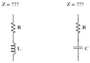
|
|
The impedance equations for the series LR and RC networks are as follows:
|
|
Notes:
Students who have taken trigonometry should recognize the radian as a unit for measuring angles. Discuss with your students why multiplying frequency (f, cycles per second) by the constant 2 p results in the unit changing to "radians per second".
Engineers often refer to w as the angular velocity of an AC system. Discuss why the term "velocity" is appropriate for w.
Question 18:
The mathematical inverse, or reciprocal, of resistance (R) is a quantity called conductance (G).
|
Is there an equivalent quantity for impedance (Z)? What is the reciprocal of impedance, and what unit of measurement is it expressed in? Hint: its symbol is Y.
Is there an equivalent quantity for reactance (X)? What is the reciprocal of reactance, and what unit of measurement is it expressed in? Hint: its symbol is B.
|
Admittance is expressed in the unit of siemens.
B = susceptance, which is the reciprocal of reactance.
|
Susceptance is also expressed in the unit of siemens.
Notes:
Ask your students where they obtained this information. Also ask them what the old (pre-siemens) unit of measurement was.
Where would such quantities be useful in AC circuit calculations? Ask your students where the quantity of conductance (G) is useful in DC circuit calculations.
Question 19:
The mathematical inverse, or reciprocal, of resistance (R) is a quantity called conductance (G).
|
Is there an equivalent quantity for reactance? What is the reciprocal of reactance, and what unit of measurement is it expressed in? Hint: its symbol is B.
|
Susceptance, like conductance (G) and admittance (Y) is expressed in the unit of siemens.
Notes:
Ask your students where they obtained this information. Also ask them what the old (pre-siemens) unit of measurement was.
Where would such a quantity be useful in AC circuit calculations? Ask your students where the quantity of conductance (G) is useful in DC circuit calculations.