The
Countersurveillance
Monitor
Counter Surveillance Monitor
"This simple-to-build, yet effective circuit can help you search out and remove
electronic eavesdropping devices."
by Vincent Vollono
and Tony van Roon
Many valuable ideas and information are lost
from businesses and home through electronic eavesdropping. In the business world, industrial
espionage is due for the most part to the fact that whosoever gets their product to the
market first is likely to reap huge profits as the others try to catch up. On the domestic
side, with so many people now self employed and conducting business from a home office, the
entrepreneur can become easy prey to those seeking to profit form the work of others.
You think domestic espionage is an unprofitable venture?... Think again! Consider that many
of the video games and applications programs that you run on your home computer are written
by hobbyists and hackers, and not by some computer scientist working for a large corporation
that has vast sums of money to spend on security. An how many corporate mergers have been
openly discussed in the informal surroundings of some CEO's home? But what is the small
businessman or private individual to do when commercially available counter-surveillance
devices can run into the hundreds and even thousands of dollars?
That's when the Countersurveillance Monitor described in this article comes in. The
Countersurveillance Monitor is a simple circuit that allows you to sweep for (detect)
electronic eavesdropping devices (more commonly called bugs).
The circuit contains no exotic parts and many of the components are so common that they may
be found in your local parts bin.
A Little Background:
Electronic bugs are very small--perhaps as small as a postage stamp--radio frequency (RF)
transmitters, that are secretly places in a room that is to be monitored. Such transmitters
emit an RF signal that can be picked up from distances of 1 mile away or more, depending
upon the sensitivity of the receiver. The receiver is, of course, used to tune in the RF
signals, thereby allowing the snooper to monitor any conversation taking place within the
covered room.
Because most bugs are RF sources, almost any wideband receiver can be used as a bug
detector. Our bug detector is essentially a highly sensitive, wideband receiver. When it
detects an RF signal ranging from 1 to 2000MHz it generates an audio output. The frequency
of the audio output goes from a low growl for a weak signal to a high pitched squeal as the
signal strength increases. In other words, the closer you get, the higher the pitch of the
audio output. That allows you to sweep an area with the Monitor to determine the location
of the transmitting device.
An important feature of the bug detector is its RF-gain stage; it is centered around a
high-gain microwave transistor, which greatly improves sensitivity. By increasing the
antenna length and setting the sensitivity control to its maximum level, extremely weak
signals can easily be located. On the other hand, by reducing the length of the antenna
and lowering the sensitivity setting, strong signals can be tracked down. Powered from a
9-volt transistor-radio battery, the circuit draws very little current, making for a long
battery life.
Circuit Description:
Figure 1 shows a schematic diagram of the Countersurveillance Monitor. The circuit, built
around a single integrated circuit (U1. an MC3403P quad op-amp), three transistors (Q1-Q3),
and a few support components, receives its input from the antenna (ANT1). That signal is
fed through a high-pass filter, formed by C1, C2, and R1, which eliminates bothersome
60-Hz pickup from any nearby power lines or line cords located in and around buildings and
home.
From the high-pass filter, the signal is applied to transistor Q1 (which provides a 10-dB
gain for frequencies in the 1- to 2000-MHz range) for amplification. Resistors R2, R3, and
R4 form the biasing network for Q1. The amplified signal is then AC coupled, via capacitor
C4 and resistor R7's (the sensitivity control) wiper, to the inverting input (pin 2) of
U1-a. Op-amp U1-a is configured as a very high gain amplifier. With no signal input from
ANT1, the output of U1-a at pin 1 is near ground potential.
When a signal from the antenna is applied to the base of Q1, it turns on, producing a
negative-going voltage at the cathode of D1. That voltage is applied to pin 2 of U1-a,
which amplifies positive-going output at pin 1. Op-amps U1-b and U1-c along with C8,
R10-R18, and Q2 are arranged to form a voltage-controlled oscillator (VCO) that operates
over the audio-frequency range. As the output of U1-a increases, the frequency of the VCO
increases. The VCO output, at pin 8 of U1-c, is fed to the input of U1-d, which is
configured as a non-inverting unity-gain (buffer) amplifier. The output of U1-d is used to
drive Q3, which, in turn, drives the output speaker.
Counter Surveillance Monitor
Parts List:

Resistors are 1/4 Watt, 5%
      R1,R8 = 220 Ohm
 R2,R10,R15 = 100K
         R3 = 39K
     R4,R21 = 470 Ohm
         R5 = 1K5
         R6 = 560 Ohm
         R7 = 5K potentiometer
         R9 = 1 Mega-ohm
R11-R13,R18 = 47K
        R20 = 100 Ohm
        R22 = 22 Ohm
        R23 = 4K7
        R24 = 1K

Capacitors:
   C1 = .001uF (1nF or 104)
C2-C7 = .01uF (10nF or 103)
   C8 = .0047uF (4.7nF)
   C9 = 4.7uF, 16V, radial-lead electrolytic
  C10 = 10uF, 16V, axial-lead electrolytic

Semiconductors:
   U1 = MC3403P quad op-amp, IC or equivalent NTE987
   Q1 = BFR90 (NTE65, MFR901) NPN microwave transistor
Q2,Q3 = PN2222 (NTE123AP) general-purpose NPN silicon transistor
   D1 = 1SS99, NTE112, or equivalent(SI-UHF TV/MIXER)
Note: The PN2222 can be replaced with an NTE123A, or any other unit,
      matching approx: Vceo=40V, Vcbo=75V, Vebo=6V, Ic=600 or 800mA.

Additional Parts and Materials:
  S1 = SPST toggle Switch
  B1 = 9V Alkaline battery
ANT1 = Telescoping antenna
SPKR = 8 ohm, 0.2 watt, 2-1/4 inch, speaker

Perfboard materials, enclosure, battery snap-on connector, battery holder
(optional), IC socket (options), wire, solder, hardware, etc.
Construction:
The Countersurveillance Monitor was assembled on a pre-etched, pre-drilled printed-circuit board that is available
*only* when ordering the full kit, listed in the Parts List section.
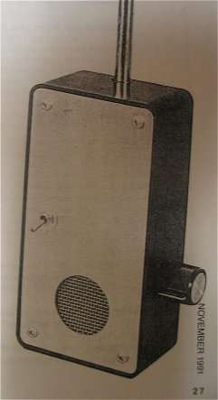
But, for those of you who'd prefer to etch your own pcb, a full-size template is shown above. The circuit was designed
to be housed in any plastic enclosure that's large enough to hold the circuit, it's 9-volt power source, a small
speaker, potentiometer R7, and of course switch S1, which can be part of the potentiometer.
Once you've etched or obtained the board via the kit, and all the parts listed in the Parts
List, construction can begin. Start by installing the passive components on the board,
guided by Fig. 3. Once the passive components have been installed and checked for
placement and orientation, install the semiconductors. The use of an IC socket for U1 is
optional; however, if you decide not to use an IC socket for U1, be careful not to overheat
the IC's terminals (pins).
Note that transistor Q1 as well as resistors R3 and R24 (which are shown as dashed lines in
Fig.3) must be installed on the copper side of the board. Since Q1 is a microwave
transistor, special care must be taken when installing it and its leads should be kept as
short as possible. After that, attach a 9-volt battery connector and the off-board
components to the board.
Circuit Checkout:
Double-check your work for the common construction errors--misoriented components, solder
bridges, misplaced components, etc.--Particularly where the transistors and diode are
concerned. Make sure that you have installed the resistors in the proper locations. When
you are satisfied that all is well, connect a 9-volt battery and turn on the power. You
should be able to adjust R7 to cause the speaker to make a sine-like sound.
By rotating R7 counterclockwise, you should be able to make the pitch go higher or lower,
turning it fully counterclockwise should stop the sound.
When using the unit to detect a bug, set the sensitivity low enough to avoid signals from
nearby radio and TV stations. It may take some experimenting at first, but it should
quickly become quite easy. When you get within a foot or two of an actual bug, there is no
mistaking it for another signal--the audio pitch will be driven to its highest frequency.
If you have problems with radio and tv signals, try adjusting the antenna to a shorter
length and then setting the sensitivity control for greater sensitivity to compensate for
the reduction in antenna length. The Countersurveillance Monitor will also pick up other
RF sources: microwave ovens, computers and peripherals, etc., but those should cause you
little concern. What you are looking for is that potted plant or lamp that has suddenly
become an RF emitter...
 Troubleshooting:
In case of trouble, the first thing to do is make sure that the battery is connected
properly and is in good working condition. If the power source and its connections are
okay, you can check the circuit using an RF source--such as a cordless telephone, a signal
generator, or a wireless microphone. Before you place the RF source near the antenna
input of the Countersurveillance Monitor, connect a DC voltmeter from the cathode of
diode D1 to ground. As you move the RF source closer to the antenna, the meter should
read an increasingly more positive voltage.
Also make sure that the antenna's connection cable is not shorted to ground (it is rather
close to the circuit's ground plane). Also make sure that none of the component leads are
left long; long leads can also cause grounding problems.
Although this is an older circuit, it should still perform nice for most bugs, except those
in the high-GigaHertz range used by government law-enforcement and special military units.
Once you get the Countersurveillance Monitor working. you can rest reasonably assured that
the homefront is free of eavesdropping devices. An whenever there is suspicion that
perhaps someone is invading your privacy, you'll be ready to tackle your hunt-and-destroy
mission!
Copyright and Credits:
Source: "Popular Electronics", November 1991. Copyright © by Vincent Vollono, and
Tony van Roon, published by Gernsback Publications, Inc. 1992. (Gernsback Publishing is no longer in business).
Document updates & modifications, all diagrams, Layout, graphics, photos, editing, ©
Copyright by Tony van Roon.
Re-posting or taking graphics in any way or form of this project is expressly prohibited by international copyright
laws.
Back to Circuits page
Copyright © 1995 Tony van Roon
Last updated: June 28, 2010