Broadcast-Band RF Amplifier
By Tony van Roon
"Unless you own a top of the line receiver or car radio, your AM reception may be as
good as it should be. The reason is that few low-to mid-price receivers and radios include RF amplifiers. By adding
on yourself, however, you can improve reception at minimal cost. The RF amp shown here uses readily available parts,
has wide bandwidth, and is very stable. In addition, by varying the values of several resistors, you can match the
amplifier's input impedance to your antenna, and its output impedance to your radio."

How it Works:
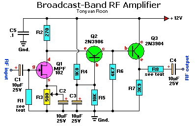
The complete schematic is shown in Fig. 1. The circuit has
frequency response ranging from 100Hz to 3MHz; gain is about 30dB.
Field Effect Transistor Q1 is configured in the common-source self-biased mode; optional resistor R1 allows you to set
the input impedance to any desired value. Commonly, it will be 50 ohms.
This signal is he direct-coupled to Q2, a common-base circuit that isolates the input and output stages and provides
the amplifier's exceptional stability.
Last, Q3 functions as an emitter-follower, to provide low output impedance (about 50 ohms). If you need higher output
impedance, include resistor R8. It will affect impedance according to this formula: R8 ~ Rout - 50. Otherwise,
connect output capacitor C4 directly to the emitter of Q3.
Construction:
The circuit can be wired up on a piece of perfboard; a PC board is not necessary, although one can
be used. However you build the circuit, keep lead lengths short and direct, and separate the input and output stages.
You may have to install the amplifier in your receiver. Otherwise, installing it in a metal case will reduce
stray-signal pickup. You'll have to provide appropriate connectors on the case. Connect the amplifier to the antenna
and radio using short lengths of coax.
The circuit has only one adjustment. Connect a source of 12-volt DC power to the circuit, and adjust R3 so that there
is a 1.6-volt drop across R2.
If you're not sure of the impedance of your antenna, connect a 500-ohm potentiometer for R1, and adjust it for best
reception. Then substitute a fixed-value resistor for the potentiometer.
You may want to follow the same procedure with the output circuit (R8), if you're not sure of your receiver's input
impedance. Common impedances are 50, 75, and 300 ohms, so the same 500-ohm potentiometer can be used.
You can connect an external antenna through the amplifier to a receiver that has only a ferrite rod antenna. Connect
the amplifier's output to a coil composed of 10-15 turns of #30 hookup wire wound around the existing ferrite core,
near the existing winding. To obtain best reception, experiment with the number of turns and their placement. You
may need to reverse the connection to the coil if the output is weak.
Parts List:
R1 = see text                C1,C2,C3,C4 = 10uF, 25volt electrolytic
R2 = 270 ohms                         C5 = 0.1uF, ceramic disc
R3 = 500 ohm potentiometer
R4 = 1K8 (1800 ohms)                  Q1 = MPF102 J-FET, or use NTE451
R5 = 10K (10,000 ohms)                Q2 = 2N3906, PNP-transistor (or use NTE159)
R6 = 4K7 (4700 ohms)                  Q3 = 2N3904, NPN-transistor (or use NTE123AP)
R7 = 3K9 (3900 ohms)                       see note about the 'AP' extension.
R8 = see text
Back to Circuits page
Page Copyright © 1995 - Tony van Roon
Project Copyright © January 1989, by D.J. Housley
