Simplest R/C Circuit
by Tony van Roon
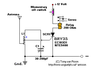
 A simple and effective receiver for actuating garage doors, starter motors, alarms, warning systems and numerous
other possibilities. The SCR, which has a very low trigger current of 30 uA is typical -- it requires an input power
of only 30 uW to activate the relay. A high Q tuned antenna circuit assures rejection of spurious signals. A whip or
wire antenna is adequate up to 100 feet from a low power transistor transmitter. A momentary-off switch resets the
circuit.
 The circuit specifies a whip or wire antenna
which just means a solid piece of wire 6-12 inches long (15-30cm). The antenna coil is experimental but you can start
with 10 to 12 turns of #22 (0.7mm) magnet wire, and 5/16" (8mm) coil diameter. Antenna wire is soldered at 1/2 turn
of the coil and the gate of the BRY35 is soldered about halfway the coil. This circuit will transmit up to 100-feet
with the above specifications @ 30uA.
The relay coil is specify's up to 200 ohm but that's just the one I had in stock. Any low-ohm relay, even at 9V or
so, should work. And a final note, don't expect too much from this circuit. The "Simplest R/C Circuit" is just that;
SIMPLE!
The BRY35 is an old semiconductor made by Philips. A good replacement would be the EC103D1, also made by Philips
(see pin-out picture for this device). NTE Semiconductors gives a replacement of NTE5405, but I have not tried it.
In my opinion, a NTE5400 (30V) or NTE5401 (60V) will work just as well. The NTE5405 is a bit overkill at 400V.
Back to Circuits Page


 The circuit specifies a whip or wire antenna
which just means a solid piece of wire 6-12 inches long (15-30cm). The antenna coil is experimental but you can start
with 10 to 12 turns of #22 (0.7mm) magnet wire, and 5/16" (8mm) coil diameter. Antenna wire is soldered at 1/2 turn
of the coil and the gate of the BRY35 is soldered about halfway the coil. This circuit will transmit up to 100-feet
with the above specifications @ 30uA.