Make Your Own Simple Rx/Tx Battery Charger with Peak Detect
by C. Blaurock
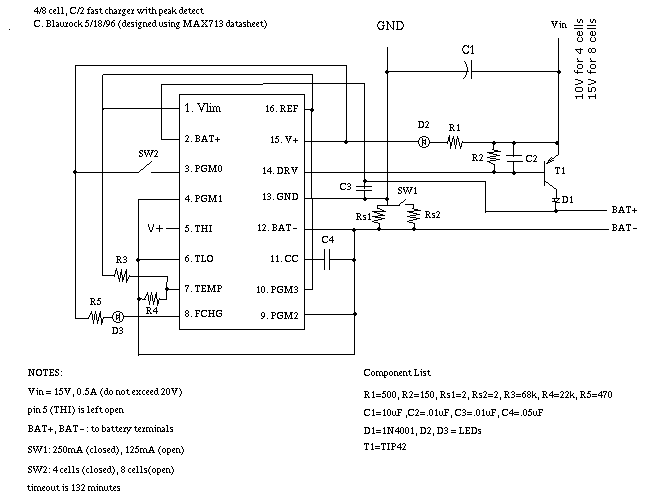
This circuit is designed to peak charge Rx and Tx batteries. It's programmed for a C/2 charge rate for 250mAh and 500mAh batteries (charge currents of 125mA or 250mA). It'll charge Rx from 12V at the field, Tx from a 15V supply (like a car w/engine running). Use a 15-18V supply to charge at home (you should be able to find wall cubes with this rating). It is based on a Maxim IC, the MAX713, which is available mail order from suppliers like DigiKey.
Operation is as follows:
1. the circuit is designed for Vin = 15V at ~0.3A. LED D2 indicates the unit has power.
2. SW1 sets the charge current for 250mAh or 500mAh packs.
3. SW2 programs the number of cells to 4 or 8 (an incorrect setting will cause peak detection to fail and will probably damage the pack).
4. fast charge starts as soon as the pack is connected. LED D3 indicates fast charge.
5. fast charge stops, and C/16 trickle charge begins, when the unit detects a battery voltage peak OR the unit times out after 132 minutes.
1. Vin should be about 1.7V/cell+1.5V. For an 8 cell Tx pack you need a 15V supply. A 9V supply will work if you are only doing 4 cell Rx packs. Try to get at least a 0.5A supply to be safe. Vin should not exceed 20V. If you want to have Vin greater than 20V, see the data sheet. (You'll need to add two components and make sure all components can handle the voltage. Also check that the transistor T1 can dissipate the extra power).
2. The resistors Rs1 and Rs2 set the charge current. If you want to do other size packs, you can change the charge current according to the relation
Icharge = 0.25V / Rs
e.g. as designed Rs = 2ohm (SW1 open) or 1ohm (SW1 closed). You can replace Rs1 and Rs2 or figure out another switching arrangement to do more than two currents.
3. you can do other pack sizes (e.g. 5 cell) by connecting PGM0 and PGM1 appropriately to V+, REF, BAT-, or leaving them open. Don't do this without studying the data sheet, or you'll kill the pack.
4. the MAX713 chip has an undervoltage detect. If the pack voltage is below 0.4V/cell when you connect it, it will start in trickle charge mode until voltage reaches 0.4V/cell then go into fast charge.
5. The unit may timeout before peak is detected (this is because not all the energy put into the battery gets converted to charge). This should only happen if the pack was almost completely depleted at the start, and it should be within 80% of full. To be sure you have the peak you can restart the fast charge (unplug then plug the pack in). You COULD add a push-open switch to open BAT+ or BAT- so that you don't need to unplug the pack to restart (I didn't think it was worth it).
I laid the circuit out on perfboard, sized to fit in a 1x2x4in Radio Shack project case. Use a DIP socket, don't solder directly to the MAX713 pins.
I didn't use a heat sink on T1. I don't think it will need it, follow your judgement if you think otherwise.
I got the Rx and Tx connectors from an old wall cube charger.
Put in some kind of test points for BAT+ and BAT- (I used banana plug sockets).
I bring in Vin and GND through a power plug, so I can plug into the 15V supply at home, but unplug and take only the small case to the field. It'll charge an Rx pack off a 12V battery. It will do the Tx off a car battery with the motor running.
Try the circuit out on some batteries/packs you can afford to lose. Use it on your pride and joy only after you know it's working correctly.
ACKNOWLEDGEMENT: this circuit was designed using information contained in the MAX713 data sheet.
DISCLAIMER: I'm not an EE and I don't design circuits for a living. This circuit SHOULD work for you, but I make no guarantees. Test it carefully.
C. Blaurock,
[email protected]