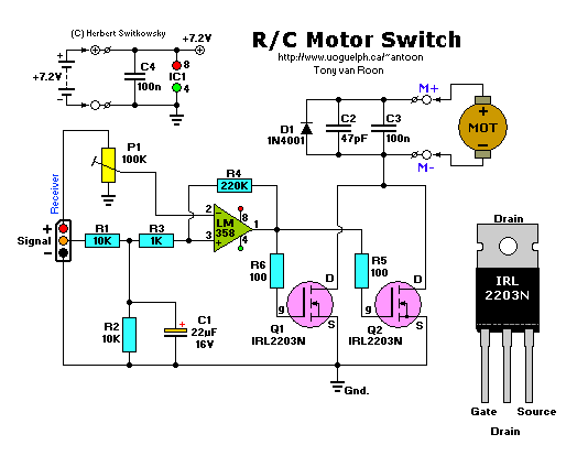
Parts List:
Resistors are 1/4W, carbon, 5% tolerance (or better).

    R1,R2 = 10K          IC1 = LM358           C1 = 22uF, 16V, electrolytic
   R3 = 1K         Q1,Q2 = IRL2203N        C2 = 47pF, ceramic
   R4 = 220K          D1 = 1N4001       C3,C4 = 100nF, ceramic
R5,R6 = 100 ohm
   P1 = 100K, trimmer

See datasheet at the bottom of the page for the IRL2203N FET's.

A parts-kit (NO PCB) is available for this circuit. [Click here]
Description:
The schematic diagram above shows an electronic Radio Control switch for use with electric motors. As you can see, the
electronic circuit is simple and straight forward, and so are the possibilities for its use. The circuit, connected
to a spare receiver channel, can only be switched 'on' or 'off', via your own transmitter. I personally use the 'gear'
setup.
This setup reacts on a 50Hz PWM-signal with a pulse width of about 1 to 2 mS. Some radio control manufacturers prefer
the signals of 40Hz. The signal, filtered by R1/R2/C1, is introduced at the non-inverting input of the as comparator
configured op-amp (IC1), a cheap and easy available 8-pin model. The other comparator is connected with a reference
voltage that can be adjusted with a Bourns trimmer potentiometer P1. If this voltage is lower than the filtered
PWM-voltage, then the output of the comparator switches 'high', biasing the FET's Q1 and Q2 who in turn supplies current
to the motor. Resistor R4 makes sure there is hysteresis, so that the comparator does not trigger on each and ever bit
of noise. The sequence reverses again on the output of the comparator when the signal voltage gets significantly lower
than the preset reference voltage.
This circuit uses two high-current FET's, made by International Rectifier, which can provide an enormous amount of
current in (short) access of 116 amp for per single FET. However, maximum output current is safely set to 75A per FET
via the thermically resistance of the FET casing. And again, this amperage can only be obtained with sufficient cooling.
With this kind of safety and the fact that sufficient cooling in R/C is just not possible, the maximum current for the
two FET's is 80A. This is still a respectable amperage and short very high currents are still possible.
No printed circuit board is available at this time. I will create one when I can find the time.
A pdf datasheet is available here: [IRL2203N.pdf]
Copyright holder of this article is Herbert Switkowsky and was first published in Elektuur's Halfgeleider Gids 2002.
(Elektor's Semiconductor Magazine, July/August 2002).
Back to Gadgets Menu page
Copyright © 2006, Tony van Roon

