In 1846, Joseph Henry was professor of natural philosophy (physics) at the College of New Jersey (now known as
Princeton University). He had published scientific articles on a wide variety of subjects, including electro magnetism,
optics, acoustics, astrophysics, molecular forces, and terrestrial magnetism, but his reputation was built primarily
on his work in basic and applied electro magnetism. Among his discoveries in electro magnetism were mutual induction,
self-induction, the electro magnetic relay--enabling him to devise the first electro magnetic telegraph that could be
used over long distances--and the concept of the electric transformer. He also invented the first electric motor.
Henry was often
referred to as the scientific successor to Benjamin Franklin. Today, it is the general opinion that Joseph Henry was
the inventor of the telegraph and not Samuel Morse, who did not have a technical background to begin with. Samuel
Morse adapted the ideas and inventions of Henry (and Vail) into his own and patented it, making him the owner.
It is certain that Joseph Henry was important to the history of the telegraph in two ways. First, he was responsible
for major discoveries in electro magnetism, most significantly the means of constructing electromagnets that were
powerful enough to transform electrical energy into useful mechanical work at a distance. Much of Morse's telegraph
did indeed rest upon Henry's discovery of the principles underlying the operation of such electromagnets.
Below are a couple other thoughts collected from the Smithsonian Institute (of which Henry was First Secretary), and
Harvard University:
"... Secondly, Henry became an unwilling participant in the protracted litigation over the scope and validity of
Samuel Morse's patents. ..."
"... Joseph Henry began his research into electro magnetism in 1827, while he was an instructor at the Albany Academy
in New York. By 1830, he achieved two major breakthroughs .... His first crucial innovation, which he demonstrated in
June 1828, was to combine Schweigger's multiplier with Sturgeon's electro magnet to obtain an extremely powerful
magnet. While Sturgeon loosely wrapped a few feet of uninsulated wire around a horseshoe magnet, Henry tightly
wound his horseshoe with several layers of insulated wire. In March 1829 he demonstrated an electro magnet with 400
turns, or about 35 feet, of insulated wire. This magnet, Henry remarked later, "possessed magnetic power superior to
that of any before known."
"... Henry did set out to demonstrate the practicality of an electro magnetic telegraph immediately after his paper
appeared. His prototype consisted of a small battery and an "intensity" magnet connected through a mile of copper
bell-wire strung throughout a lecture hall. In between the poles of this horseshoe electro magnetic he placed a permanent
magnet. When the electro magnetic was energized, the permanent magnet was repelled from one pole and attracted to the
other; upon reversing battery polarity, the permanent magnet returned to its original position. ... Henry caused the
permanent magnet to tap a small office bell. He consistently demonstrated this arrangement to his classes at Albany
during 1831 and 1832."
In short, this man, Joseph Henry, was a scientist and physicist by heart and a true teacher to his students. As a
reward, they (not his students) stole his ideas and scientific experiments. For that reason I'm convinced that Morse
was a fraud, preying on the ideas and inventions (like the telegraph) of others and putting his patent on it (obtained
on October 3, 1837). I do credit Samuel Morse, however, for the morse-code, which is still used to this date and no
person without a 5-wpm morse-code qualification exam can call him/herself a Advanced Radio Amateur! (see Fig. a).
Since this important day in 1836, when Joseph Henry transmitted a small electrical current down a wire to energize a
remote coil and the completed circuit ringing a bell some 150 years ago, the relay has undergone steady evolution and
today's relays are far removed from the crude and clumsy relays of Henry's days. In our millennium, solid-state has
replaced the actual relay in many circuits, especially in AC applications. To sum it all up, the relay (and solenoids)
have survived the tube, transistor, and integrated circuit (IC) eras.
Basically, a relay is an electrically operated
switch, and actually the predecessor of the transistor. Solenoids are relays also but the very large types which
carry huge amounts of current. Relays are the
smaller types. Relays come in three types: electro mechanical,
solid-state, and so-called hybrids which are a combination of the first two. There are also some specialized types
that fall into neither category but I will deal with them later in this tutorial. Lets take electro-mechanical types
first, they are available in three main models; armature, plunger, and reed. The Armature Relays are the
oldest (see Fig. 1) but elegant. Plenty turns of very fine magnet-wire are wound
around an iron core to form an electro-magnet.
The movable metal armature has an electrical contact that is positioned over a fixed contact attached to the relay
frame. A spring holds the armature up so that the movable and fixed contacts are normally separated (open). When the
coil is energized, it attracts the pivoting armature and pulls it down, closing (make) the SPST contacts and completes
the power circuit. Vice-versa, this relay can be made to open the contacts instead of closing them, or can do both
either way. The armature relay is pretty old and no longer used in new applications, they do still exist however and
are being used still at the time of writing this document.
The Plunger-Relay type have a plunger instead of a pivoting armature, as shown in Fig. 2
and uses a solenoid action to close the contacts. The electro magnetic core is hollow and a metal rod or plunger
extends halfway through it when the relay is not energized.
When energized, the coil draws the plunger in and a shorting-bar, attached to the end of the plunger, closes the
contacts. When the coil is de-energized, the spring (which is mounted over a section of the plunger) retracts the
plunger and positions the assembly in the idle position breaking the contacts.
The coil plunger design allows much greater contact travel than the pivoting armature design, thus allowing wide
contact separation. The increased space allows plunger systems to be used with higher voltages than armatures. The
higher closing force of the solenoid permits the use of larger contacts and provides greater current handling
capability. One application of a plunger-type relay is an electronic lock or door opener.
Since their inception, electro-magnetic relays have
improved in sensitivity, switching complexity, current handling, response time, and reliability. It allowed for
miniaturization in radios, cassette recorders, Radio Control(R/C), NASA, cameras, and other home electronics applications.
Being relatively small, Reed Relays fill the demand for all sorts of 'small' stuff. The use of flexible reeds and
self-attraction distinguishes the reed relay, see Fig. 3, from other electro magnetic
relays. Note that the drawing shows the reed-relay without the actuator coil. The contacts are mounted on thin metal
strips (reeds) and hermetically sealed in a glass tube. This tube is surrounded by a magnetic coil which, when
activated, magnetizes the reeds and causing them to attract each other which closes the contacts. When the coil is
de-energized, the spring tension in the reeds causes them to separate again. This type of design has the advantages
of high speed operation, long life, and very low price. One of the great advantages reed relays share with other
electro magnetic relays is the relative ease with which they can be fitted with multiple contacts. As in the armature
and plunger designs, the contact mechanisms can be stacked to provide multiple circuit-close or open designs, or even
a combination of both, all activated by a single coil. In reed relays, multiple contact pairs, but in individual
tubes, can be stacked and used with a single coil in a very small space. This is not a feature of solid-state relays.
Some Relay-driver Examples using regular components:
Fig. 4Sound-Activated type. The relay remains dormant until the
op-amp activates upon sound via the electret-microphone. The input stage is a regular off-the-shelf 741 operational
amplifier and connected as a non-inverting follower audio amplifier. Gain is approximately 100 which you can raise
by increasing the value of R2. The amplified signal is rectified and filtered via C3, D1/D2, and R4 to an acceptable
DC level. Potentiometer R5 is used to set the audio level to a desired sensitivity value to activate the relay via
transistor Q1. Diode D3 is mounted over the relay coil to absorb sparks. The op-amp configuration in this particular
drawing needs a dual voltage power supply which can be made from two 9-volt batteries.
The circuit in Fig. 4a is similar but with less component.
Fig. 5
This relay driver boosts the input impedance with a regular 2N3904 transistor. Very common driver. It can drive
a variety of relays, including a reed-relay. Transistor Q1 is a simple common-emitter amplifier that increases the
effective sensitivity of the 12 volt relay coil about a 100 times, or in other words, the current gain for this circuit
is 100. Using this setup reduces the relay sensitivity to a few volts. R1 restricts the input current to Q1 to a
safe limit (the impedance is equal to the value of R1 plus 1K). Diodes D1 and D2 are EMF dampers and filter off any
sparking when the relay de-energizes.
Fig. 6-1
is a delayed turn-on relay driver and can produce time delays for up to several minutes with reasonable accuracy.
The 14001 (or 4001) CMOS gate here is configured as a simple digital inverter. Its output is fed to the base of a
regular 2N3906 (PNP) transistor, Q1, at the junction of resistor R5 and capacitor C2. The input to IC1 is taken
from the junction of the time-controlled potential divider formed by R2 and C1. Before power is applied to the circuit,
C1 is fully discharged. Therefore, the inverter input is grounded, and its output equals the positive supply rail;
Q1 and RY1 are both off under this circuit condition. When power is applied to the circuit, C1 charges through R2,
and the exponentially rising voltage is applied to the input of the CMOS inverter gate. After a time delay
determined by the RC time constant values of C1 and R2, this voltage rises to the threshold value of the CMOS
inverter gate. The gate's output then falls toward zero volts and drives Q1 and relay RY1 'ON'. The relay then remains
on until power is removed from the circuit. When that occurs, capacitor C1 discharges rapidly through diode D1 and R1,
completing the sequence. The time delay can be controlled by different values for C1 and R2. The delay is approximately
0.5 seconds for every µF as value for C1. The delay can further be made variable by replacing R2 with a fixed and
a variable resistor equal to that of the value of R2. Taken the value for R2 of 680K, it would be a combination of
180K for the fixed resistor in series with a 500K variable trim pot. The fixed resistor is necessary.
Fig. 6-2
is configured in an automatic turn-off mode. It shows how the circuit function of Fig. 6-1 can be reversed so that the
relay turns on when power is applied but turns off again automatically after a preset delay. This response is obtained by
modifying the relay-driving stage for an NPN transistor like the 2N3904. It is worth noting again that the circuits in
Fig. 6-1 and Fig. 6-2 each provide a time delay of about 0.5 seconds for every micro-Farad in the value
of capacitor C1. This permits delays of up to several minutes. If desired, the delay periods can be made variable by
replacing resistor R2 with a fixed and variable resistor in series whose nominal values are approximately
equal of the total value of R2 (680K).
Fig. 7
This is an accurate long-duration time delay driver, switchable between 1 and 10 minutes or 10 to 100 minutes and whose
function does not depend on electrolytic capacitors. Film dielectric caps have been selected. IC1 is configured as a
free-running astable multivibrator which frequency is divided down by IC2, a 14020 (or 4020) CMOS 14-stage, ripple-carry
binary divider. Consequently relay RY1 turns on as soon as switch S1 is closed, and it turns off again when the 8192nd
astable pulse arrives. This method provides time periods ranging from 1 to 100 minutes, depending on the switch setting
of S2.
Solid State Relays:
"Solid-State-Relay" (referred to as 'SSR' for short) means switching without any mechanical means. A solid-state relay
is nothing more than a electronic switch, which can be a Triac, SCR, HexFet, or a High Speed MosFet, and an opto-isolator.
Some are application dependent.
Control-to-load isolation is provided either by opto-isolators or transformers. Solid-state relays are available in
AC and DC versions; Fig. 8a/b/c/d/e shows typical block diagrams. All approaches shown
use an opto-isolator to separate the control and drive segments.
Virtually all solid-state relays are Single-Pole Single-Throw, Normally Open
(SPST-NO) devices, where the outputs turn on in response to a control voltage. The majority take operating power from
the control I/O, although some require separate DC logic power. The simplest DC input circuits use an LED optoisolator
and series current-limiting resistor.
The resistor is usually sized for a 5-volt logic input, and results in a specified "ON" range of 3-6 volts DC. For
wider operating ranges (typically 4-32 volts DC), the resistor is replaced by a constant-current diode. Then, AC input
circuits rectify and filter the control input before applying it to the LED. Typical AC/DC LED currents can vary from
5 to 22mA.
AC and DC Outputs:
The optoisolator photocurrent is amplified and used to drive whatever output device the relay is connected to, whether a
transistor for DC outputs, a thyristor for AC, or a power MOSFET for either. The power for the drive circuitry is
taken either from the output load or is supplied separately. In some MOSFET designs, the photocurrent is sufficient
to drive the output device.
Table 1 summarizes typical specifications.
Normally, DC output devices like those in Figs. 8-Fc and Fd use an NPN transistor and may include a Zener diode across
the output for transient suppression. The transistor will drop some voltage in the "ON" state, and the drive circuit
will need some current to operate. Typical output drop is 1-2 volts at the full rated load current, while the
"OFF"-state leakage may range from approximately 10µA-1mA.
Most AC output devices include zero-voltage-switching circuitry. Logic detects when the AC load voltage crosses zero
(changes polarity) and delays the triac turn-on pulse until then. The triac turns on a the next zero crossing after
the input goes high. Once triggered, it remains on until its current goes to zero. Zero-voltage and zero-current
switching minimize transients and ElectroMagneticInterference (EMI). The RC snubber in Fig. 8-Ff
suppresses rapid voltage changes that can inadvertently turn on the thyristor.
In some applications, having the output turn on instantly is desirable. Relays referred to as "random turn-on" are
designed without zero-voltage switching. Turn-off still occurs at zero-current, due to the inherent latching effect of
thyristors. As with DC output relays, the thyristor drops voltage while conducting, while the drive circuitry requires
power to operate. In addition, th snubber passes AC leakage in the "OFF" state. Typical "ON"-state voltage 1.6 volts,
while "OFF"-state leakage is 2-20mA for 60Hz power.
With recent advantages in power MOSFET's, solid-state relays can be designed with lower "ON"-state voltage drops, and
greatly reduce "OFF"-stage leakage. These MOSFET's (and HexFets) offer bidirectional current flow, near-zero
gate-drive current, no inherent source-to-drain offset voltage, and low "ON"-state (rDS) resistance and "OFF"-state
leakage.
Most FET-output relays are housed in Dual-Inline-Packages (DIP's). Their main use is as a replacement for reed relays,
where low offset and low leakage are important, and for control of low-power AC/DC loads. High power AC loads are
best controlled by thyristors, which are easily controlled for zero-voltage turn-on; they also offer inherent
zero-current turn-off, and produce lower output-voltage drop at high currents.
However, FET design involves tradeoffs in voltage, current and resistance specs. In particular, high-voltage FET's
have higher "ON" resistances, making them unsuitable for switching high-current line-voltage loads. Typical DIP relays
have 70-500mA current ratings, "OFF"-state leakage resistances of 100 MegaOhms or more, and "ON" resistances from about
one ohm for a 60-100 volt rating, to 25-50 ohms for a 300-400 volt rating. Switching times range from 10-100µSec.
I/O Isolation:
The majority of solid-state relays use opto-isolators. All of at least 1.5 kilo-volt RMS I/O breakdown, and 2.5 or 4
kilo-volt ratings are common. Most of them have been rated, listed, or approved by safety agencies like UL, CSA, and
VDE. Transformer coupling is also used to isolate solid-state relays.
Fig. 8-Fc shows a transformer-coupled AC-output relay; DC and AC/DC FET relays are also
available with transformer coupling. The control input powers an oscillator, the output which is coupled through a
small pulse transformer to trigger the output thyristor. Circuitry of the type shown produces random turn-on
operation; transformer-coupled relays generally don't include zero-voltage switching circuitry.
Transformer coupling allows faster switching. The oscillator frequency is typically 1-3MHz, resulting in switching times
as low as 1µSec. Opto-isolators exhibit slower response, with times for DC versions typically 10 to 100µSec.
They can be designed for slightly higher temperatures, being free of LED limitations. However, achieving breakdown
voltages above 1.5 kilovolts is easier using optical techniques.
Hybrid Relays:
Hybrid relays marry reed relays with a solid-state power output. Fig. 8-Fb shows a
thyristor version; DC outputs are also offered. The hermetically sealed reed contacts switch only low power, and last
10 million operations or even longer. The turn-on time is that of the reed relay, about 1 mSec. Other hybrid relays
are the reverse, using a solid-state input amplifier driving a reed-relay output, the obvious advantage being high
input sensitivity. The term "hybrid" sometimes describes construction technique, rather than method of operation.
In some catalogs you'll find hybrid solid-state relays with no mechanical components at all.
Self-Powered and Buffered Relays:
So far, all the relays that have been discussed until now have been "self-powered," in that they take operating power
from the applied signals. All models, whether optoisolated, transformer coupled, of hybrid, require approximately
5-50mA at their inputs. Some, notably thyristor-output relays with zero-voltage switching, also take operating
power from output loads, although none require separate power connections.
Buffered relays offer improved input sensitivity at the expense of needing separate DC power, and are usually used in
systems that already include DC power supplies (not as stand-alone devices).
Fig. 8-Fd shows a buffered DC-output relay. The input circuitry and the LED are powered
from a separate logic supply, allowing the logic input current to be typically 25-250µA.
Due to near-zero gate current, power MOSFet's can be driven directly from a
series stack of photodiode junctions. The "photo voltaic-generator" stack from International Rectifier shown in
Fig. 8-Fe is constructed using IC fabrication techniques, and exposes a series of photo diodes
to LED illumination. No operating power is required from the load.
Package Styles:
Solid-State relays are generally grouped into DIP's, power relays, and I/O modules. DIP relays are available with
transistor (DC), thyristor (AC), or MOSFET (AC/DC) outputs, and with optoisolator or transformer coupling. Most power
relays are used to switch AC power, and use thyristor switching with optoisolator coupling. Transistor (DC) outputs
and transformer coupling are also available. I/O modules are always opto-coupled, and don't offer MOSFET outputs.
Table 2--Relay Contact arrangements are designated as Forms A-D. Form A
is normally open until the coil closes it, while Form B is normally closed until the coil opens it. Forms C and D use
double-throw contacts, arranged as break-before-make (Form C) or make-before-break (Form D).
Safety Issues:
Building an SSR requires putting 115/220 volts AC on a printed
circuit board. From an electrical point of view, that can be
perfectly safe. However, it is good practice to cover all printed circuit tracks on the 115/220VAC side with a silicon
sealer, varnish, lacquer, or even nail polish. Couple layers will do fine. Also, try to use only isolated Triacs
(where the case is electrically isolated from the Triac), and ground the heat sink to the AC safety wire (earth ground,
or green wire).
Choosing a Triac:
There are three basic requirements when choosing the output Triac. First is to make sure that it will handle the
voltage required. The minimum for a 115-volt AC line requires a 200-volt Triac. A 220-volt line requires a 400-volt
Triac. Remember that those are the minimum so, for a few cents more, it pays to use the next highest voltage rating.
The next requirement is current. A 6-amp Triac will handle 6 amps only if it is properly heat sinked. As a word of
warning, motors draw a lot more current on start-up than they do during normal operation, sometimes as much as ten
time more. Keep that in mind when you design your own.
The third requirement is the gate current. The Motorola MOC3010 optoisolator will provide about 100 milliamps of
drive current for the output Triac. That should be adequate for any Triac you can find in a TO-220 package. Just in
case it is not sufficient for your design, you can use a transistor as a current-sink.
Although not really a strict requirement, an isolated Triac is good practice and a good safety precaution. Isolated
Triacs (usually listed in catalogs as iso-tab) provide electrical isolation from the electrical connections to the
case. Early Triacs were not normally isolated. That meant that you had to use mica washers and thermal grease.
Thermal grease is still a good idea, but the mica washer isn't required for isolated Triacs. If you don't know
whether or not your Triac is isolated, simply measure the resistance from each lead to the case. An isolated Triac
will measure open on all three leads. Warning: The Radio Shack 400-volt, 6-amp Triac (part number 276-1000) will work well
but is NOT isolated. You must use a TO-220 mica washer and thermal grease if you plan to use that device.
Zero-Voltage Switching:
I can hear you mumbling already... "what the heck is zero-voltage switching..."? In normal operation the trigger side
of the relay is totally asynchronous to the AC side. That means that a trigger could occur during any part of the sine
wave. If the trigger occurs near a peak (90 or 270 degrees), a large current will flow into the load almost instantly.
That creates a lot of RFI (Radio Frequency Interference) and also is very hard on the filament of ordinary light
bulbs. In order to prevent that, zero-crossing SSR's accept the trigger at any time but delay turning on the AC load
until the next time the AC voltage passes through zero volts. Now you know. I personally don't use any other type.
Construction of a SSR:
Below is good working Solid State Relay using an opto-isolator and a Triac. Use of a printed circuit board is
highly recommended but not required. Remember to isolate the AC tracks when you're all done!
For a simple SSR, an optoisolator such as the Motorola MOC3010 or the NTE3047 will be sufficient. For a zero-crossing
SSR, a MOC3031 or NTE3049 will do. May companies make optoisolators. Make sure yours has a "Triac output" and that
the pinouts are compatible with your design. Table 2 shows some typical Triac output optoisolator specifications. The
models shown are already a decade old but still widely used and available.
Again, although the SSR can certainly be build without using a PCB, using one makes assembly using the diagram in
Fig. 9 a snap.
The only precaution, other than the one about working with 115/220/220 AC volts, is to heatsink the Triac. If you leave
the leads on the Triac long, it should be simple matter to find some heat sink to attach to the Triac. Just remember
to connect the heat sink to earth-ground. Even if you're using an isolated tab Triac, the earth ground is still
necessary. Otherwise you should buy your solid-state relays from a reliable company--don't build them yourself.
Remember that SSR's can only switch an AC line. Trying to switch a DC line will result in a relay that closes but
never opens... Have fun!
Couple More Circuits To Play With:
Fig. 10: This circuit shows a pair of CMOS NOR gates which form a
push-button-activated one-shot multivibrator relay-switching circuit that provides delays up to several minutes with
resonable accuracy. The relay turns on as soon as the START switch S1 is closed. However, it turns off again after
a preset delay of about 0.5 seconds per microFarad (uF) of the value of capacitor C2. The two CMOS gates are
configured as a manually-triggered monostable multivibrator whose output is fed to the relay through R4 and transistor
Q1.
Fig. 11: This one shows a 'long-range timer relay' switching circuit which spans
1 minute to 20 hours in three ranges using a three-step, two-deck mechanical rotary switch. IC1, the 555
timer/oscillator does the time
IC2 (4017) is a CMOS decade counter IC, a five-stage Johnson counter with 10 decoded outputs. Inputs include a CLOCK,
a RESET, and a CLOCK INHIBIT signal. This IC, together with IC3 and the 3-step rotary switch, can provide a maximum
division ratio of 81,920 making it possible to time for periods up to 20 hours or so. Circuits like this are used in
battery chargers and area security lighting systems with time-controlled turn-off.
IC3 (4020) is a CMOS 14-stage, ripple-carry binary divider. Normally a 'high' would occur as soon as switch S1 is
closed and a 'low' when the 8192nd astable pulse arrives. All counter stages of IC3, the 4020, are master-slave
flip-flops. The state of a counter advances one count on the negative going transition of each input pulse, and a
high level on the RESET line resets the counter to its all zeros state. All inputs and outputs are buffered.
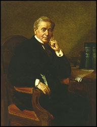 First a bit of history about the remarkable
development of this 'relay' device. Joseph Henry (1797-1878), a brilliant US scientist who invented and used the
electro-magnetic relay in his university laboratory. His low-power electro magnet could control a make-and-break switch
in a high-power circuit. Henry believed the potential was in the relay's use as a control system in manufacture, but
he was only really interested in the science of the electricity. The relay was a laboratory trick to entertain
students. Samuel Morse later used Henry's relay device, after re-designing it using thinner wire, to carry morse-code
signals over long kilometers of wire.
First a bit of history about the remarkable
development of this 'relay' device. Joseph Henry (1797-1878), a brilliant US scientist who invented and used the
electro-magnetic relay in his university laboratory. His low-power electro magnet could control a make-and-break switch
in a high-power circuit. Henry believed the potential was in the relay's use as a control system in manufacture, but
he was only really interested in the science of the electricity. The relay was a laboratory trick to entertain
students. Samuel Morse later used Henry's relay device, after re-designing it using thinner wire, to carry morse-code
signals over long kilometers of wire. Henry was often
referred to as the scientific successor to Benjamin Franklin. Today, it is the general opinion that Joseph Henry was
the inventor of the telegraph and not Samuel Morse, who did not have a technical background to begin with. Samuel
Morse adapted the ideas and inventions of Henry (and Vail) into his own and patented it, making him the owner.
Henry was often
referred to as the scientific successor to Benjamin Franklin. Today, it is the general opinion that Joseph Henry was
the inventor of the telegraph and not Samuel Morse, who did not have a technical background to begin with. Samuel
Morse adapted the ideas and inventions of Henry (and Vail) into his own and patented it, making him the owner. "... Henry did set out to demonstrate the practicality of an electro magnetic telegraph immediately after his paper
appeared. His prototype consisted of a small battery and an "intensity" magnet connected through a mile of copper
bell-wire strung throughout a lecture hall. In between the poles of this horseshoe electro magnetic he placed a permanent
magnet. When the electro magnetic was energized, the permanent magnet was repelled from one pole and attracted to the
other; upon reversing battery polarity, the permanent magnet returned to its original position. ... Henry caused the
permanent magnet to tap a small office bell. He consistently demonstrated this arrangement to his classes at Albany
during 1831 and 1832."
"... Henry did set out to demonstrate the practicality of an electro magnetic telegraph immediately after his paper
appeared. His prototype consisted of a small battery and an "intensity" magnet connected through a mile of copper
bell-wire strung throughout a lecture hall. In between the poles of this horseshoe electro magnetic he placed a permanent
magnet. When the electro magnetic was energized, the permanent magnet was repelled from one pole and attracted to the
other; upon reversing battery polarity, the permanent magnet returned to its original position. ... Henry caused the
permanent magnet to tap a small office bell. He consistently demonstrated this arrangement to his classes at Albany
during 1831 and 1832." In short, this man, Joseph Henry, was a scientist and physicist by heart and a true teacher to his students. As a
reward, they (not his students) stole his ideas and scientific experiments. For that reason I'm convinced that Morse
was a fraud, preying on the ideas and inventions (like the telegraph) of others and putting his patent on it (obtained
on October 3, 1837). I do credit Samuel Morse, however, for the morse-code, which is still used to this date and no
person without a 5-wpm morse-code qualification exam can call him/herself a Advanced Radio Amateur! (see Fig. a).
In short, this man, Joseph Henry, was a scientist and physicist by heart and a true teacher to his students. As a
reward, they (not his students) stole his ideas and scientific experiments. For that reason I'm convinced that Morse
was a fraud, preying on the ideas and inventions (like the telegraph) of others and putting his patent on it (obtained
on October 3, 1837). I do credit Samuel Morse, however, for the morse-code, which is still used to this date and no
person without a 5-wpm morse-code qualification exam can call him/herself a Advanced Radio Amateur! (see Fig. a). Since this important day in 1836, when Joseph Henry transmitted a small electrical current down a wire to energize a
remote coil and the completed circuit ringing a bell some 150 years ago, the relay has undergone steady evolution and
today's relays are far removed from the crude and clumsy relays of Henry's days. In our millennium, solid-state has
replaced the actual relay in many circuits, especially in AC applications. To sum it all up, the relay (and solenoids)
have survived the tube, transistor, and integrated circuit (IC) eras.
Since this important day in 1836, when Joseph Henry transmitted a small electrical current down a wire to energize a
remote coil and the completed circuit ringing a bell some 150 years ago, the relay has undergone steady evolution and
today's relays are far removed from the crude and clumsy relays of Henry's days. In our millennium, solid-state has
replaced the actual relay in many circuits, especially in AC applications. To sum it all up, the relay (and solenoids)
have survived the tube, transistor, and integrated circuit (IC) eras. Relays are the
smaller types. Relays come in three types: electro mechanical,
solid-state, and so-called hybrids which are a combination of the first two. There are also some specialized types
that fall into neither category but I will deal with them later in this tutorial. Lets take electro-mechanical types
first, they are available in three main models; armature, plunger, and reed. The Armature Relays are the
oldest (see Fig. 1) but elegant. Plenty turns of very fine magnet-wire are wound
around an iron core to form an electro-magnet.
The movable metal armature has an electrical contact that is positioned over a fixed contact attached to the relay
frame. A spring holds the armature up so that the movable and fixed contacts are normally separated (open). When the
coil is energized, it attracts the pivoting armature and pulls it down, closing (make) the SPST contacts and completes
the power circuit. Vice-versa, this relay can be made to open the contacts instead of closing them, or can do both
either way. The armature relay is pretty old and no longer used in new applications, they do still exist however and
are being used still at the time of writing this document.
Relays are the
smaller types. Relays come in three types: electro mechanical,
solid-state, and so-called hybrids which are a combination of the first two. There are also some specialized types
that fall into neither category but I will deal with them later in this tutorial. Lets take electro-mechanical types
first, they are available in three main models; armature, plunger, and reed. The Armature Relays are the
oldest (see Fig. 1) but elegant. Plenty turns of very fine magnet-wire are wound
around an iron core to form an electro-magnet.
The movable metal armature has an electrical contact that is positioned over a fixed contact attached to the relay
frame. A spring holds the armature up so that the movable and fixed contacts are normally separated (open). When the
coil is energized, it attracts the pivoting armature and pulls it down, closing (make) the SPST contacts and completes
the power circuit. Vice-versa, this relay can be made to open the contacts instead of closing them, or can do both
either way. The armature relay is pretty old and no longer used in new applications, they do still exist however and
are being used still at the time of writing this document. Since their inception, electro-magnetic relays have
improved in sensitivity, switching complexity, current handling, response time, and reliability. It allowed for
miniaturization in radios, cassette recorders, Radio Control(R/C), NASA, cameras, and other home electronics applications.
Being relatively small, Reed Relays fill the demand for all sorts of 'small' stuff. The use of flexible reeds and
self-attraction distinguishes the reed relay, see Fig. 3, from other electro magnetic
relays. Note that the drawing shows the reed-relay without the actuator coil. The contacts are mounted on thin metal
strips (reeds) and hermetically sealed in a glass tube. This tube is surrounded by a magnetic coil which, when
activated, magnetizes the reeds and causing them to attract each other which closes the contacts. When the coil is
de-energized, the spring tension in the reeds causes them to separate again. This type of design has the advantages
of high speed operation, long life, and very low price. One of the great advantages reed relays share with other
electro magnetic relays is the relative ease with which they can be fitted with multiple contacts. As in the armature
and plunger designs, the contact mechanisms can be stacked to provide multiple circuit-close or open designs, or even
a combination of both, all activated by a single coil. In reed relays, multiple contact pairs, but in individual
tubes, can be stacked and used with a single coil in a very small space. This is not a feature of solid-state relays.
Since their inception, electro-magnetic relays have
improved in sensitivity, switching complexity, current handling, response time, and reliability. It allowed for
miniaturization in radios, cassette recorders, Radio Control(R/C), NASA, cameras, and other home electronics applications.
Being relatively small, Reed Relays fill the demand for all sorts of 'small' stuff. The use of flexible reeds and
self-attraction distinguishes the reed relay, see Fig. 3, from other electro magnetic
relays. Note that the drawing shows the reed-relay without the actuator coil. The contacts are mounted on thin metal
strips (reeds) and hermetically sealed in a glass tube. This tube is surrounded by a magnetic coil which, when
activated, magnetizes the reeds and causing them to attract each other which closes the contacts. When the coil is
de-energized, the spring tension in the reeds causes them to separate again. This type of design has the advantages
of high speed operation, long life, and very low price. One of the great advantages reed relays share with other
electro magnetic relays is the relative ease with which they can be fitted with multiple contacts. As in the armature
and plunger designs, the contact mechanisms can be stacked to provide multiple circuit-close or open designs, or even
a combination of both, all activated by a single coil. In reed relays, multiple contact pairs, but in individual
tubes, can be stacked and used with a single coil in a very small space. This is not a feature of solid-state relays.
 Fig. 5
This relay driver boosts the input impedance with a regular 2N3904 transistor. Very common driver. It can drive
a variety of relays, including a reed-relay. Transistor Q1 is a simple common-emitter amplifier that increases the
effective sensitivity of the 12 volt relay coil about a 100 times, or in other words, the current gain for this circuit
is 100. Using this setup reduces the relay sensitivity to a few volts. R1 restricts the input current to Q1 to a
safe limit (the impedance is equal to the value of R1 plus 1K). Diodes D1 and D2 are EMF dampers and filter off any
sparking when the relay de-energizes.
Fig. 5
This relay driver boosts the input impedance with a regular 2N3904 transistor. Very common driver. It can drive
a variety of relays, including a reed-relay. Transistor Q1 is a simple common-emitter amplifier that increases the
effective sensitivity of the 12 volt relay coil about a 100 times, or in other words, the current gain for this circuit
is 100. Using this setup reduces the relay sensitivity to a few volts. R1 restricts the input current to Q1 to a
safe limit (the impedance is equal to the value of R1 plus 1K). Diodes D1 and D2 are EMF dampers and filter off any
sparking when the relay de-energizes. Fig. 6-1
is a delayed turn-on relay driver and can produce time delays for up to several minutes with reasonable accuracy.
Fig. 6-1
is a delayed turn-on relay driver and can produce time delays for up to several minutes with reasonable accuracy. on until power is removed from the circuit. When that occurs, capacitor C1 discharges rapidly through diode D1 and R1,
completing the sequence. The time delay can be controlled by different values for C1 and R2. The delay is approximately
0.5 seconds for every µF as value for C1. The delay can further be made variable by replacing R2 with a fixed and
a variable resistor equal to that of the value of R2. Taken the value for R2 of 680K, it would be a combination of
180K for the fixed resistor in series with a 500K variable trim pot. The fixed resistor is necessary.
on until power is removed from the circuit. When that occurs, capacitor C1 discharges rapidly through diode D1 and R1,
completing the sequence. The time delay can be controlled by different values for C1 and R2. The delay is approximately
0.5 seconds for every µF as value for C1. The delay can further be made variable by replacing R2 with a fixed and
a variable resistor equal to that of the value of R2. Taken the value for R2 of 680K, it would be a combination of
180K for the fixed resistor in series with a 500K variable trim pot. The fixed resistor is necessary.
 "Solid-State-Relay" (referred to as 'SSR' for short) means switching without any mechanical means. A solid-state relay
is nothing more than a electronic switch, which can be a Triac, SCR, HexFet, or a High Speed MosFet, and an opto-isolator.
Some are application dependent.
"Solid-State-Relay" (referred to as 'SSR' for short) means switching without any mechanical means. A solid-state relay
is nothing more than a electronic switch, which can be a Triac, SCR, HexFet, or a High Speed MosFet, and an opto-isolator.
Some are application dependent.
 Most FET-output relays are housed in Dual-Inline-Packages (DIP's). Their main use is as a replacement for reed relays,
where low offset and low leakage are important, and for control of low-power AC/DC loads. High power AC loads are
best controlled by thyristors, which are easily controlled for zero-voltage turn-on; they also offer inherent
zero-current turn-off, and produce lower output-voltage drop at high currents.
Most FET-output relays are housed in Dual-Inline-Packages (DIP's). Their main use is as a replacement for reed relays,
where low offset and low leakage are important, and for control of low-power AC/DC loads. High power AC loads are
best controlled by thyristors, which are easily controlled for zero-voltage turn-on; they also offer inherent
zero-current turn-off, and produce lower output-voltage drop at high currents. Fig. 8-Fc shows a transformer-coupled AC-output relay; DC and AC/DC FET relays are also
available with transformer coupling. The control input powers an oscillator, the output which is coupled through a
small pulse transformer to trigger the output thyristor. Circuitry of the type shown produces random turn-on
operation; transformer-coupled relays generally don't include zero-voltage switching circuitry.
Fig. 8-Fc shows a transformer-coupled AC-output relay; DC and AC/DC FET relays are also
available with transformer coupling. The control input powers an oscillator, the output which is coupled through a
small pulse transformer to trigger the output thyristor. Circuitry of the type shown produces random turn-on
operation; transformer-coupled relays generally don't include zero-voltage switching circuitry. Hybrid Relays:
 Due to near-zero gate current, power MOSFet's can be driven directly from a
series stack of photodiode junctions. The "photo voltaic-generator" stack from International Rectifier shown in
Fig. 8-Fe is constructed using IC fabrication techniques, and exposes a series of photo diodes
to LED illumination. No operating power is required from the load.
Due to near-zero gate current, power MOSFet's can be driven directly from a
series stack of photodiode junctions. The "photo voltaic-generator" stack from International Rectifier shown in
Fig. 8-Fe is constructed using IC fabrication techniques, and exposes a series of photo diodes
to LED illumination. No operating power is required from the load. Table 2--Relay Contact arrangements are designated as Forms A-D. Form A
is normally open until the coil closes it, while Form B is normally closed until the coil opens it. Forms C and D use
double-throw contacts, arranged as break-before-make (Form C) or make-before-break (Form D).
Table 2--Relay Contact arrangements are designated as Forms A-D. Form A
is normally open until the coil closes it, while Form B is normally closed until the coil opens it. Forms C and D use
double-throw contacts, arranged as break-before-make (Form C) or make-before-break (Form D). Building an SSR requires putting 115/220 volts AC on a printed
circuit board. From an electrical point of view, that can be
perfectly safe. However, it is good practice to cover all printed circuit tracks on the 115/220VAC side with a silicon
sealer, varnish, lacquer, or even nail polish. Couple layers will do fine. Also, try to use only isolated Triacs
(where the case is electrically isolated from the Triac), and ground the heat sink to the AC safety wire (earth ground,
or green wire).
Building an SSR requires putting 115/220 volts AC on a printed
circuit board. From an electrical point of view, that can be
perfectly safe. However, it is good practice to cover all printed circuit tracks on the 115/220VAC side with a silicon
sealer, varnish, lacquer, or even nail polish. Couple layers will do fine. Also, try to use only isolated Triacs
(where the case is electrically isolated from the Triac), and ground the heat sink to the AC safety wire (earth ground,
or green wire).