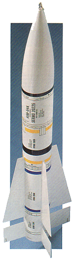
Model Rocket Strobe Light
by Anthony Charlton
"Launch a model rocket on the darkest night, and find it in a flash no matter where it lands!"
 "I shot an arrow in the air, it fell to earth I
don't know where". When Longfellow penned those words in the 1800's, he must have been thinking about my model rocketry
career! The bane of a model rocket or r/c airplane hobbyist is losing a carefully constructed and painstakingly
finished model in shrubbery, or trees. But those days are over.
Our Rocket Strobe sends out a highly visible S.O.S. for up to 2 hours, providing ample time to locate and recover
the model. It also makes dramatic night launches a reality, with the blue-white flash of the Strobe visible throughout
the flight sequence.
"I shot an arrow in the air, it fell to earth I
don't know where". When Longfellow penned those words in the 1800's, he must have been thinking about my model rocketry
career! The bane of a model rocket or r/c airplane hobbyist is losing a carefully constructed and painstakingly
finished model in shrubbery, or trees. But those days are over.
Our Rocket Strobe sends out a highly visible S.O.S. for up to 2 hours, providing ample time to locate and recover
the model. It also makes dramatic night launches a reality, with the blue-white flash of the Strobe visible throughout
the flight sequence.
Seeing the Light:
Invented in 1923 by Dr. Harold E. Edgerton, Xenon flash lamp is the light-producing device for our Strobe. Flash lamps
produce a short-duration, high-intensity pulse of light by converting energy stored in a capacitor to visible light.
Each flash of the Strobe lasts about 500 micro-seconds. For that brief instant, the flash is as bright as a 4KW
(4000 Watt) lamp! It is the high intensity of the light pulse that produces long-range visibility--yet, the Strobe
requires very little energy input.
Basic Strobe Circuit:
A strobe circuit has four basic parts. (See Fig. 1). The first is the power supply, which must be capable of producing
about 300 volts from a 9-volt battery. That high voltage is required to sustain the arc within the lamp after
triggering. Second, we need a capacitor to store energy. The luminescence provided by the Strobe is directly related
to the value of the capacitor, or to the amount of energy that the capacitor can store.
Third, we need a triggering circuit to produce a very high voltage pulse to ignite the lamp. A typical ignition pulse
has an amplitude of 4000-volts, and is several microseconds in duration. The trigger pulse is capacitively couple to
the Xenon gas inside the lamp. When enough atoms are ionized by the pulse, and if the capacitor has enough charge on
it, the gas fully conducts. Light output begins after conduction, and continues until the charge on the capacitor
drops to about 50 volts. The lamp shuts itself off at that point, to renew the cycle after the voltage build up
again.
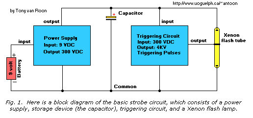 Last, we need a Xenon flash lamp; which is available at Radio Shack/Tandy and other outlets or use one from an old
camera flash. There are several different shapes and designs of flash lamps. We shall use a small, straight type in
our Strobe.
Last, we need a Xenon flash lamp; which is available at Radio Shack/Tandy and other outlets or use one from an old
camera flash. There are several different shapes and designs of flash lamps. We shall use a small, straight type in
our Strobe.
Size and Weight:
In order to be successfully lifted, our Strobe needs to be small, efficient, and light. Weight and size saving is
accomplished by miniaturizing the power supply. Surplus electronics suppliers often have camera electronic flash boards
left over from manufacturing overruns. Those boards contain tiny transformers that are capable of producing hundreds of
volts from a battery-powered driver circuit. Or check out old used cameras with an electronic flash. Good sources are
flea markets or used equipment stores like Salvation Army, or Value Village, etc.
To drive them with maximum efficiency, we use a hex FET, and a pulse-width-modulator (PWM) circuit. That combination
results in maximum power output from the smallest size and weight unit, while providing an adjustable flash rate.
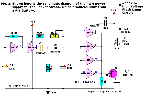
Strobe Circuit Construction:
Referring to Fig. 2, gate U1-a (one-sixth of a CD4584 CMOS Schmitt Trigger) is configured as an oscillator. With the
values shown, the oscillator operates at 6 KHz. You may need to experiment with different frequencies by using the
different values of C1 and R1 to obtain maximum output if you use a transformer other than the one specified in the
Parts List.
Gate U1-b squares up the output of U1-a and feeds a square ware to C2, C2, R2, R3, D1, and R4. Trimmer potentiometer R4
controls the duty cycle of the resulting pulse. When R4 is set to its maximum resistance, the maximum pulse-width and
power is available from the circuit.
The remaining gates (U1-c, U1-d, U1-e, and U1-f) serve to amplify and invert the output of the PWM (Pulse Width Modulator)
part of the circuit. The amplified pulse is fed to the IRFZ20 Hex FET, whose upper low on-state resistance of only
0.07 ohm switches the primary of T1 with great force. Pull down resistor R5 keeps the IRFZ20 totally off during the
logic '0' state of gates U1-c to U1-f. The output is rectified by D2, and is used to power the Strobe's flash lamp circuit.
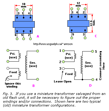 A word is needed about miniature transformers.
Most units have an accessory winding used in self oscillation circuits
powered by bipolar transistors. That winding is not needed, since we have our own on-board PWM oscillator circuit. A
simple test with an ohmmeter will reveal that low-resistance feedback winding. Do not confuse it with the low resistance,
heavy gauge primary winding. Typical transformer configurations are shown for you in Fig. 3, as examples.
A word is needed about miniature transformers.
Most units have an accessory winding used in self oscillation circuits
powered by bipolar transistors. That winding is not needed, since we have our own on-board PWM oscillator circuit. A
simple test with an ohmmeter will reveal that low-resistance feedback winding. Do not confuse it with the low resistance,
heavy gauge primary winding. Typical transformer configurations are shown for you in Fig. 3, as examples.
Another consideration is that lots of transformers are connected for European and Oriental active-negative circuits.
(Akin to driving the wrong side of the road to us!) That confusion is easily overcome by identifying the start of the
primary and secondary windings. Connect the start of each winding as indicated in Fig. 2.
When in doubt, you may make a simple power indicator from a NE-2 neon lamp and a 220K (220,000 ohm), half watt resistor,
connected in series. Connect the lamp to the cathode of D2; and the lamp will glow much more brightly when the right
combination of winding polarity is connected.
The Flash-Lamp Circuit:
Previously, we mentioned that there is a relationship between lamp luminance and the size of the main capacitor. A
unit rated at 33µF will provide 2 watt/seconds (W/S) of light output. With our circuit, the flash rate is
adjustable from one every 30 seconds to one every 4 seconds using trimmer potentiometer R4. You may want to
experiment with different capacitor values to obtain the desired light output at the desired flash rate.
For instance, a 10µF capacitor in our circuit will produce about 1/3 of the maximum attainable light level
while providing a rate of nearly one flash per second at R4's maximum setting. That rate would be better suited to
night photography of the flight sequence. A slower, brighter flash is ideal for recovering the rocket in the daytime,
when visibility of the flash is at its worst.
A long battery life (at a slow flash rate) is possible by setting R4 to minimum. We strongly recommend the use of a
9-volt NiCad battery, to save on battery costs. Keep in mind though, that the so-called 9-volt NiCad does NOT actually
contain 9 volts but rather around 7.6 volts (6 x 1.25/cell) and so the flash will not be as bright as with a regular
Alkaline battery. I don't care about the cost of alkaline batteries. I buy 12 for $5.99. They come cheap these days.
Regular carbon batteries work poorly because of their inability to supply the current needed for the strobe circuit.
The average current consumption of the strobe at 9-Volts was measured at 230mA at maximum flash rate setting, and
45 mA at the minimum setting. Nickel Cadmium batteries give a slower flash because of their lower voltage.
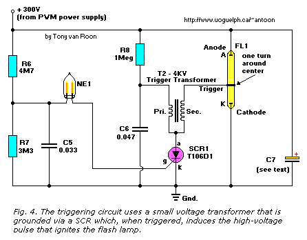
The triggering circuit uses an interesting trick. (See Fig. 4). A small transformer, T2, is grounded via an SCR
connected to its primary. When SCR1 switches on, the charge on C6 quickly travels through T2's primary and the SCR
to ground. That induces a high voltage pulse in T1's secondary winding, which ignites FL1. A simple and inexpensive
trigger circuit kicks on SCR1 when the charge on C7 is high enough to sustain the arc inside FL1. A voltage divider,
consisting of R6 and R7, ensures that roughly 300 volts is stored in C7 before the neon lamp, NE1, fires. Neon lamps
are designed to fire at different voltages. The common NE-2 type neon lamp used in our circuit fires at about 120-volts
DC. When NE1 fires, it dumps the charge stored in C5 to the gate of SCR1. That in turn, produces a trigger pulse
that is applied to flash lamp LF1, causing it to ignite, which allows you to find your rocket in a flash!
Speaking of flashes, let's look at different ways to attach a flash lamp to your rocket, rocket stability, what type of
engines can loft your "bird", and a few suggestions for multiple strobes to increase visibility.
 In our prototype, the flash lamp is attached to the end of the
rocket's nose cone with silicone glue. The electronics are handily located in the nose, and the battery is held by a
snap-in holder designed to withstand the shock and vibration of parachute deployment without losing the battery.
The author used a combination 9-volt battery-snap connector and holder assembly.
In our prototype, the flash lamp is attached to the end of the
rocket's nose cone with silicone glue. The electronics are handily located in the nose, and the battery is held by a
snap-in holder designed to withstand the shock and vibration of parachute deployment without losing the battery.
The author used a combination 9-volt battery-snap connector and holder assembly.
A balsa wood plug is held securely in place by silicone, which also seals the components inside the nose cone, as well
as providing an anchor point for the parachute, and shock-absorbing rubber cord leading to the rocket's body.
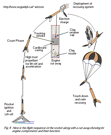
Strong assembly techniques are needed for the nose-cone/electronics package. The nose cone must withstand considerable
force at the apex of flight when the rocket engine activates its ejection charge. There is nothing gently about the
hefty charge of black powder that pops off the nose cone and deploys the parachute! Fig. 5 shows the parts of a rocket
engine, and their function. Be sure to use enough silicone (without disturbing vertical, rotational balance) for
good strength.
Weight must be minimized to allow your bird to lift off, and attain maximum height. Soft grades of balsa wood are the
lightest, and weight savings may be gained by careful assembly of the electronics on a small board, using a minimum of
solder. All said, our Strobe added 3-1/2 ounces to the rocket's weight. You may also save weight by not painting the
model with too many coats of finish if it's to fly a Strobe.
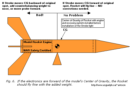
If the electronics are ahead of the model's center of gravity (CG), the rocket should fly fine with the added weight.
If, for some reason, you locate the electronics or battery behind the rocket's CG, a counter-balancing weight must
be added to the nose to bring the CG back to its normal position. A rocket's CG is determined by its balance point
with an unused engine installed. (See Fig. 6.)
A flash lamp may be attached to the rocket's nose, body, or fins. Be aware that the delicate flash lamp needs breakage
protection. A rigid clear piece of plastic tubing placed around the lamp affords additional breakage protection. Plug
the open end with a tapered balsa or plastic plug to preserve the rocket's aerodynamic sleekness. Use of a short,
sturdy flash lamp, cushioned in Silicone may work fine, as it did with our model.
The parachute's size must be increased to compensate for the added weight: 40 square inches of parachute area per ounce
of weight is recommended. All told, our rocket weighed 13.5 ounces, so 540 square inches of chute area was needed. We
replaced the 18-inch chute that came with the model with two 24-inch ones. That gave about 900 square inches, which
gently delivers the model to earth.
If you need to use more than one chute, attach each chute's shroud lines to a snap swivel (which can be found at the
fishing tackle shops). Those handy little gizmos reduce the chance of the line tangling (which can lead to disaster)
and enables you to clip on or remove chutes in a jiffy. More than one parachute means you will have to pack each
carefully. Try not to wind the lines too tightly around the chutes, and use plenty of flame-proof wadding between the
chutes and engine. Dusting the chutes with plain talcum powder lets them slide out freely during the engines's
ejection phase and they unroll quicker when in the air.
The finished model's weight is an important consideration in engine selection. To launch successfully, the model must
be less than the Maximum Lift Weight (MLW) of the engine type selected. Weight can really creep up on you (as all
dieters know!). Our model, called the Phoenix, weighed 11.6 ounces, with the engine and strobe installed. After it
was painted, the paint added 1.9 ounces! That put the total weight at 13.5 ounces, very close to the MLW of the
engine we used.
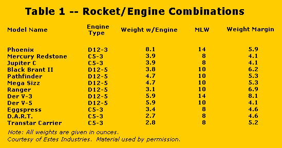 Table 1 is an (Estes) listing of
some (older) rocket/engine combinations that will lift off with the Strobe onboard.
Each model was selected to provide a reasonable weight, and a body size large enough to hold a 9-volt battery. The
weight margin is what's left over for the Strobe, paint, battery, and so forth. The rockets are sold in kit form,
and manufactured by Estes Industries. Other designs may work, provided that you use lightweight batteries, and built
the rocket and Strobe using minimal-weight methods. I guess the NiMh (Nickel Metal Hydrate) batteries these days
would be the best choice. Not only are they much lighter then NiCads, they supply more current longer at true 9 Volts.
Table 1 is an (Estes) listing of
some (older) rocket/engine combinations that will lift off with the Strobe onboard.
Each model was selected to provide a reasonable weight, and a body size large enough to hold a 9-volt battery. The
weight margin is what's left over for the Strobe, paint, battery, and so forth. The rockets are sold in kit form,
and manufactured by Estes Industries. Other designs may work, provided that you use lightweight batteries, and built
the rocket and Strobe using minimal-weight methods. I guess the NiMh (Nickel Metal Hydrate) batteries these days
would be the best choice. Not only are they much lighter then NiCads, they supply more current longer at true 9 Volts.
Multiple strobes add a very interesting touch. We used up to six flash lamps, strung in parallel, all operating
from the same power supply. The light output appears to be equally divided among multiple lamps if they are all of
the same type. To get the same brightness per lamp, you will have to increase the value of electrolytic capacitor C7
(see Fig. 4). For instance, with 3 lamps, C7 would need to be three times larger to provide each lamp with a high
brightness, but the total light output would be tripled. Increase C6 to 0.1µF when using more than one lamp
in parallel. The higher capacitance causes a greater charge to be dumped across T1's primary (and hence, a larger
secondary current), which guarantees the ignition of all lamps.
Construction:
Well, by now you are an expert on power supplies, strobes, rockets, and aerodynamics; so let's roll up our sleeves, and
get to work!
You may make a pcb, or wire the electronics on perfboard (which we did). A universal printed-circuit-board worked fine.
As you assemble the circuit, be mindful of the need to minimize weight. Use just enough solder to make a good joint.
Trim away excess space on your mounting board.
Wherever possible, use miniature (or smt) components. A NiCad or NiMH battery will save you quite a bit of weight
(1.25 ounces vs almost 2 ounces for an alkaline unit). The NiCad gives a good 15 minutes of flashing at high rate, and
over 1 hour on slow. Even better results with the NiMH type.
The power supply layout is not critical, but you must pay attention to the high-voltage output of the trigger transformer.
That little guy puts out over 4,000 volts, and while it does not look too dangerous it packs quite a nasty wallop!
Dress the secondary leads away from other components; a half inch is recommended. The wires leading to capacitor C7
and the trigger transformer should be short, and if on the outside of the rocket, glued flat to avoid excess air drag.
If you run the wires inside the body, make sure that they won't become tangled in the recovery system! Also, the ejection
gases will quickly rot the insulation on wires; if they are in an exposed area, jacket and seal them in heat shrink tubing
or the kind of plastic tubing sold for aquarium air lines.
Wire size is not critical; we had fine luck with #26 stranded hook-up wire. Make sure flash-lamp polarity is observed.
The end with the large round electrode is the cathode, which is always connected to ground. Some flash lamps have a
trigger-wire already attached to one end, but on those that don't, one wrap of bare wire around the lamp's center will
do the the trick. Secure the wire with a tiny dab of epoxy or Crazy glue to the glass.
Make sure that the leads to the lamp are well insulated at the splices. A connector is handy to have in the circuit
leading to the lamp. That way, the electronics can be quickly disconnected for testing or adjustment. Eventually, the
lamp burns out and has to be replaced, but only after many, many flashes. The author calculates the lamp listed in the
Parts List will last around 20,000 flashes. That's over 20 hours of continuous at a high flash rate, and represents
many rocket flights.
 To get the best efficiency, it's necessary to keep C4 close to Q1 (see Fig. 2). That ensures a "reservoir" of current
to draw from as Q1 switches. Usually, Q1 does not need any heatsink. Different types of mini and micro transformers
and component tolerances may necessitate a small heatsink on Q1 if it gets too hot to comfortably hold. Sometimes,
due to winding differences, you will need to increase C4 to 470µF or 680µF in order for the PWM circuit
to work efficiently. A 16-volt capacitor is satisfactory for use with a 9-volt battery.
To get the best efficiency, it's necessary to keep C4 close to Q1 (see Fig. 2). That ensures a "reservoir" of current
to draw from as Q1 switches. Usually, Q1 does not need any heatsink. Different types of mini and micro transformers
and component tolerances may necessitate a small heatsink on Q1 if it gets too hot to comfortably hold. Sometimes,
due to winding differences, you will need to increase C4 to 470µF or 680µF in order for the PWM circuit
to work efficiently. A 16-volt capacitor is satisfactory for use with a 9-volt battery.
Build the PWM part of the circuit first. You should test it before installing the hex FET and T1. That is easily
accomplished by using a small speaker with a 10-µF capacitor attached to one lead. Connect the other lead to ground,
and the free end of the capacitor to pins 6, 8, 10, and 12 of U1. By adjusting R4, you will be able to hear the volume
of the tone getting louder or quieter as R4 varies the pulse width. Once the PWM circuit works, attach the mini
transformer, using Figs. 2 and 3 as a guide to polarity. Use proper precautions to minimize static, and install Q1.
The +300-volt output may be tested with a neon lamp. Resistor R4 varies the brightness of the lamp somewhat.
Put together the Strobe section of the circuit (see Fig. 4.) keeping in mind the high-voltage output of T2. Once
you have all the parts assembled, it is a good idea to give the finished board and components several light coats of
an insulating spray to prevent shorts and high-voltage arcing. A product such as "Acrylic Coating" (which has a
dielectric strength of 2,000 volts per 0.001 inch) or other material for coating printed-circuit boards works well.
Don't coat R4, or it won't work anymore! Also, don't spray anything on the flash lamp, although you may insulate
the ends to prevent arcing outside the flash tube.
 Testing:
Before installing the electronics in the rocket, and gluing everything down, check to see that the Strobe is operating
correctly. With a 9-volt input and using the parts specified, you should see a flash every 4 seconds on the high
setting, and about 30 seconds on the low setting of R4. You'll note the first flash takes quite a while to appear
(depending on the quality of C7), usually 10-15 seconds on high, and a few minutes on low.
The reason for that is that C7, the large electrolytic that stores the energy to light the flash lamp, has to "polarize"
if it has been sitting idle for a long while. Leakage within the capacitor is maximum when voltage is first applied,
and it has to charge and discharge several times before leakage subsides and absorbs less power. If that problem
exists, run the Strobe from another 9-volt battery before launch and wait until the flash rate goes up. Then, you may
install your flight battery, and let 'er rip
If you can get accurate specifications, select C7 for low leakage. Most miniature, recent-style capacitors work fine.
In our prototype Strobe, we left out an on/off switch, opting instead to simply install the 9-volt battery when
launching. You may install a switch, or leave it out as desired.
Finally, remember to observe sensible practices when flying your rocket. If it gets caught in a power line, or high
in a tree, leave it! No project is worth risking one's life! Fly in clear areas, especially for night launches, and
observe wind direction, launch angle, expected trajectory, and landing site to optimize your changes of successful
recovery. Happy Flying!
Parts List and other components:
Semiconductors:
   Q1 = IRFZ20 Hex FET (Digi-Key IRFZ20-ND)
   D1 = 1N4148, general purpose silicon signal diode
	 D2 = 1N4007, 1A, 1000-PIV, general purpose rectifier diode
	 U1 = CD4584 Hex Schmitt Trigger, IC
 SCR1 = T106D1, C106D1, ECG5457, NTE5457, etc. 400-volt/4-amp, sensitive gate
        Silicon Controlled Rectifier

Resistors:
All Resistors are 5%, 1/4-watt, unless otherwise noted.
 R1 = 6800 ohm (same as 6K8)
 R2 = 10,000 ohm (same as 10K)
 R3 = 820 ohm
 R4 = 1000 ohm, trimmer potentiometer
 R5 = 1000 ohm (same as 1K)
 R6 = 4.7 Megohm (same as 4M7)
 R7 = 3.3 Megohm (same as 3M3)
 R8 = 1 Megohm	(1M)

Capacitors:
 C1 = 0.022 µF, 10% stable temperature coefficient.
                (DigiKey P1016 or equivalent)
 C2 = 2200 pF, 20% stable temperature coefficient.
              (DigiKey P3222 or equivalent)
 C3 = 330 pF, ceramic disc (DigiKey P4106 or equivalent)
 C4 = 330 to 680 µF, 16WVDC, miniature electrolytic
 C5 = 0.033 µF, 250 WVDC (DigiKey E2333 or equivalent)
 C6 = 0.047 µF, 400 WVDC (DigiKey E4473 or equivalent)
 C7 = 33 µF (or value to suit, see text) 350 WVDC miniature electrolytic

Additional Parts & Materials:
 FL1 = Xenon Flash Lamp
 NE1 = NE-2 type, 120 volt neon lamp
  T1 = see text
  T2 = 4KV trigger transformer
Printed Circuit Board or perfboard materials, 9-volt alkaline battery,
battery holder, wire, solder, enclosure or shrink sleeving, etc.
For Radio Shack part numbers click on this RS data sheet.
I fully support this project. Most parts can be obtained via your local Radio Shack or Tandy
store. I will answer all questions but via the message forum only. Tony's Message Forum can be accessed
via the main page, gadgets, or circuits page.
Copyright and Credits:
The original project was written by Anthony Charlton. Reproduced from Hands-On Electronics, January 1989, by
permission of Gernsback Publishing, Inc. Document updates & modifications, all diagrams, PCB/Layout redrawn by Tony
van Roon. Re-posting or taking graphics in any way or form of this project is expressily prohibited by international
copyright © laws.
Back to Gadgets page
Copyright © 2002 - Tony van Roon