Chute Control for Model Rockets
by Tony van Roon
"Deploy your rocket parachute after a pre-set, adjustable, time delay. This device is
similar to the STX-10"

Parts List:
Rx = see text
C1 = 47uF, 25V,  Electrolytic or Tantalum (35V)
C2 = 0.01uF (10nF) ceramic (if needed for noise)

U1 = MC1455P, LMC55CM, NTE955MC, or similar 8-pin CMOS timer.
Q1 = IRFZ42, MPT5N06, IRF513, BUZ11 or similar N-Channel MosFET. They all work.
D1 = 1N4148, NTE519, 1N914, etc. (optional)
D2 = 1N4001, 1N4002, 1N4004, etc.
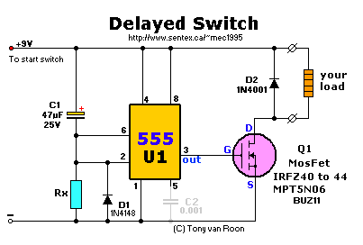
When the 'Start' switch is pressed C1 will slowly charge via R1 keeping pin 6/2 high until it reaches 1/3 of +V and then switches low driving
output pin 3 of the 555 open. Pin 3 will bias the gate of the MosFET Q1 and closing the solid-state contacts over the Drain and Source.
The value of Rx can be determined with the formula T = R x C in seconds. Rx is in K, C is in Farads, T is in seconds.
Example: R=470K, C=47uF. Time = 470 x 0.047 = 22.09 seconds. Measured value at 9 volt was 21.2 seconds.
If you know the time you can calculate the resistor value: R = T.C (Resistor value = seconds divided by capacitance).
A note on using the correct battery type; An regular 9 volt Alkaline battery is suggested. A 9 volt NiCad is not really
9 volt but rather 7.5 volt (1.25 per cell x 6).
The variation between calculated and measured value is due to component tolerances. To find an almost perfect match,
use a 1Mega-ohm, 10-turn trimmer potentiometer and adjust the delay until you find the setting of your choice. Then
measure the ohm's value of the trimmer pot and replace with a permanent resistor with a 2% (or better) tolerance. Use
a metal-film if you can, they are more temperature stable and more precise. Same for the capacitor. A tantalum type
is preferred if you need a precise delay time.
C2 is a regular 0.01uF (10 nanoFarad) filter capacitor but may not be needed. It is used to filter off noise in
some applications like spikes coming from the brushes of an electric motor.
Use a low-power CMOS type for the timer to make the battery last longer. The regular 555 will also work, just needs
more power. D2, the 1N400x diode, is a must. Otherwise backcross EMF flutter between the Drain and +V may
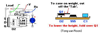
cause accidental activation of the 'load'. You can fold this MosFet over the D2 diode to keep everything as flat
as possible. This circuit can be powered by any voltage between +5 and +15V.
Only if you find that there is too much signal on the gate, insert a 150 ohm or so resistor between pin 3 and the
gate of Q1. Also, if your choice of MosFet seems to "sticky" in the "ON" position, change your MosFet to a BUZ11 or
IRFZ42 or 44. They have a low Rds'on' and will perform better.
Below are the PCB and Lay-out for your convenience. I'm considering making a SMT version which shrinks the whole
thing to less than the smallest postal stamp and very light. You can shrink the pcb further if you want an smt version. The smt version of the 555
is very tiny and similar for the MosFet. Or you can try cutting of the tab of the MosFet. This will save on weight and size and will not hamper
performance since the use of the circuit will only be momentary until the chute(s) are deployed.


I fully support this project. Most parts can be obtained via your local Radio Shack or Tandy
store. I will answer all questions but via the message forum only. Tony's Message Forum can be accessed
via the main page, gadgets, or circuits page.
Copyright and Credits:
Copyright © 2002, Tony van Roon. Advice and hints provided by rocketeer
Craig Oliver.
Re-posting or taking graphics in any way or form of this project is expressily prohibited by international
copyright © laws.
Back to R/C Gadgets page
Copyright © 2002 - Tony van Roon


