Train Horn, Two-tone Train Horn
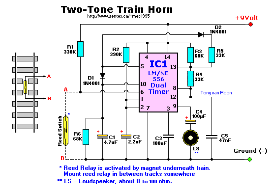
Parts List for 556 version
   R1 = 330K                        C1 = 4.7uF/16volt, electrolytic
   R2 = 390K                        C2 = 2.2uF/16volt, electrolytic
R3,R6 = 68K                         C3 = 100nF, ceramic
R4,R5 = 33K                         C4 = 100uF/16volt, electrolytic
   S1 = on/off switch               C5 = 47nF, ceramic
   Re = Reed Relay (glass tube)     LS = 8 Ohm, 0.25-2watt. Others may work too.
  IC1 = NE556 (or use two 555's)         (I used a 2"/2W type)
D1,D2 = 1N4001
With this circuit you can electronically simulate the noise of a diesel-train horn. The sound is triggered
automatically as the train reaches a desired place on the track so you can produce the sound as the train approaches
stations, level crossings, etc.
The circuit can be built simply by using one 556 or two 555 timers. The rest of the parts are readily available and
not critical. The output power from the two-Tone train horn is adequate to drive a miniature loudspeaker directly so
all that is required is a single 9V alkaline battery or a 9VDC wall-adaptor.
How it Works:
For the explanation, we use the second schematic diagram with the two 555's. The sound generating part of this
circuit is formed by IC2, a 555 connected as an astable multivibrator. The frequency of the sound varies with the
overall charge and discharge times of capacitor C4. So, when the junction of D1 and 2 is high, the frequency of
oscillation is set by the current through R4 plus that through R5, charging the capacitor. Similarly, when the junction
of D1, 2 is low the frequency is set by the current through R5, (no current can flow through R4). When the charge
current is less, therefore, the frequency is lower.
Integrated Circuit IC1, another 555, forms a monostable multivibrator with an 'on' time of about 2 seconds. The
multivibrator output (pin 3) is connected directly to the junction of D1/D2, and hence when the monostable is 'on' the
frequency is higher than when it is 'off'.
A reed switch under the track is operated by a magnet attached to the train as it passes and this triggers IC1.
Click here-==> to listen.
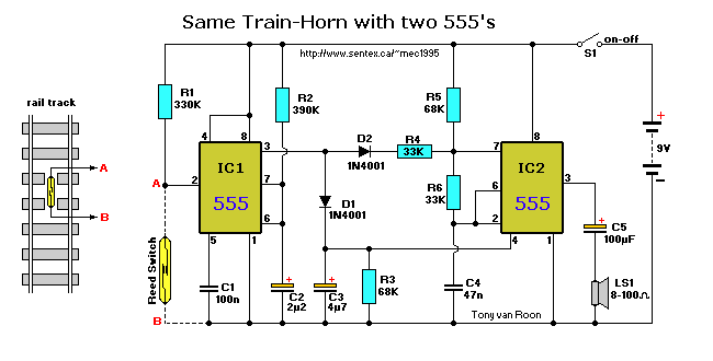
Parts List for 555 version
     R1 = 330K                        C1 = 100nF, ceramic
     R2 = 390K                        C2 = 2.2uF/16volt, electrolytic
  R3,R5 = 68K                         C3 = 4.7uF/16volt, electrolytic
  R4,R6 = 33K                         C4 = 47nF, ceramic
     S1 = on/off switch               C5 = 100uF/16volt, electrolytic
     Re = Reed Relay (glass tube)     LS = 8 Ohm, 0.25-2watt. Others may work too.
IC1,IC2 = NE555                            2 Watts or more is required for better
  D1,D2 = 1N4001                           sound. (prototype used a 3"(76mm), 2W type)
The 555 version is available as a KIT: [Train Horn].
Construction:
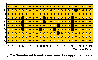
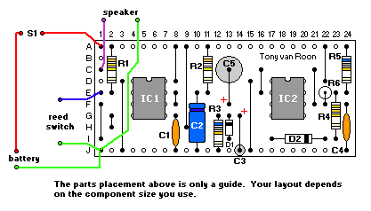
Veroboard construction (perf-board) on a standard sized 10 strip by 24 hole board means that this project is quite
easy to build.
The usual procedures and precautions should be followed but you will find that very few of the components are critical.
In fact you may like to experiment with different values to get other sounds.
Make your track breaks first with either the purpose-made tool or simply a hand-held 1/8" drill bit. Next, insert all
links and IC sockets, followed by resistors, capacitors and finally semiconductors.
Figure 2 shows connection details of the project along with overlay and underside-board views and you should
follow it carefully.
To generate the two-tone sound automatically, mount a reed switch under the track at whatever location you require. A
magnet attached to the bottom of the train will operate the reed switch as it passes. You can connect as many reed
switches as you wish, in parallel, to trigger the sound at various places around the track. Maker sure that the contacts
of the reed switch are facing upwards or it will not work. When the reed switch is inside a reed-relay it doesn't matter
which side is up since the magnetic field surrounds the reed. With a single magnet however, the contacts must be facing
'up'.
Final Notes:
Each timer produces a high and a low tone. If you don't want to fiddle with the reed relay that is fine too; use a
momentary 'on' pushbutton switch insteed. The reed relay may required a strong magnet (experiment with it). Make sure
the reed relay is positioned in such a way that the magnet is able to close the contacts, and the reed relay contacts
are facing upwards. With the correct loudspeaker (I used an oval 2-watt, 8 ohm type which I salvaged out of an old
computer sound system), the sound is very realistic! The larger loudspeakers can get very low audio.
Back to Gadgets Menu page
Copyright © 1996, Tony van Roon
Train Horn, Two-tone Train Horn