"Learn how to use 7-segment display devices. Although not as popular as LCD's, current wise, the 7-segment display is a real cost saver and
lets you choose between multiple colors and display sizes."
© by 2010, Tony van Roon

 A bit of History:
Like most of my tutorials, lets start with a bit of history and background information. Although I have to admit there is not a whole lot of
background information available specific to the development of 7-segments. Since 7-segment technology is based on the LED, I suggest reading the
history of the LED technology here.
Captain Henry Joseph Round (2 June 1881, Kingswinford, Staffordshire, England�17 August 1966, Bognor Regis) was one of the early pioneers of radio
and received 117 patents. He was a personal assistant to Guglielmo Marconi.
He laid the foundation for LED technology, however, no practical use was made of the discovery for several decades.[18] Independently, Oleg
Vladimirovich Losev published "Luminous carborundum [[silicon carbide]] detector and detection with crystals" in the Russian journal Telegrafiya i
Telefoniya bez Provodov (Wireless Telegraphy and Telephony).[19] Losev's work languished for decades.
Seven segment displays can be found in patents as early as 1908 (in U.S. Patent 974,943, F.W. Wood invented an 8-segment display, which displayed the
number 4 using a diagonal bar), but did not achieve widespread use until the advent of LEDs in the 1970s. They are sometimes even used in
unsophisticated displays like cardboard "For sale" signs, where the user either applies color to pre-printed segments, or (spray)paints color through
a seven-segment digit template, to compose figures such as product prices or telephone numbers.
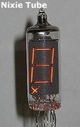
 The photograph on the right is a socalled 'nixie-tube' and they were nicknamed just as 'nixies'. Nice to look at when they were in working
condition but prone to failure because of the heat of the tube.
The photograph on the right is a socalled 'nixie-tube' and they were nicknamed just as 'nixies'. Nice to look at when they were in working
condition but prone to failure because of the heat of the tube.
Early wrist watches, back in the 70's, used this type of display but they used so much current that the display was normally switched off. To see the
time you had to push a button. But it was progress on the run and the led wristwatch had a very short life. Shortly after that Casio came out with
the first series of LCD watches with lots of options. I have one of those early Casio watches. They don't have sound and are kindah thick but run
very accurate and the battery lasted two to three years. What I like about the 7-seg's is that they are very forgiving in use. There are many
choices in size, straight or italic, color or just white displays. I have used them all. My last project was a small powersupply (PowerPlay) for my
son's Science Fair project and this power supply used four 7-segment displays for the panel meter. Beautiful working powersupply, up to two amp and
up to 24V. The drivers were regular TTL 74LS47 IC's.
The problem with the design of TTL IC's was that non-decimal inputs (10 through 15) show up as incomplete digits or odd patterns. The MC4511 does not have
these problems and this IC is mainly used today. However, decades ago the 7447 series TTL were cheap and were bought by the dozen.
How it works:
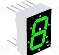
Lets start with the 7-segment display itself. A 7-segment display is an assembly of light emitting diode-bars (segments) each which can be powered
individually. They are arranged and labeled as shown in the diagram, in the form of an '8' in hexadecimal form. When all the segments are powered
on, the display show the number 8. Powering up segments a, b, c, d, and g will display the number 3. Each individual 7-segment can display numbers
from 0 to 9. The 'dot' or dp represents the decimal point, which can be selected either on the left or right side of the display.
The numeric 7-segment display can also show a limited number of other characters, limited only by your own fantasy, but usually 'a to g'. But 'L',
'I', 'O', 'S', and a couple others are also possible.
Some problems may arise with the 'X' and 'H' and '2' and 'Z' for example but there are ways to get around that. Anyways, the regular 7-segment
display is numeric only. However, Alpha-numeric displays are available but cost a little more. Although the price drop of LCD�s tend
to overtake the market, I believe 7-segment display still have a real purpose because of its high illumination, like, display boards in darker areas
like train stations. Even the count-down display of NASA is still 7-segment based and the countdown can be read easily even in bright sunlight.
Talking about cost, because of the decades long popularity of the 7-segment display, there are tons of them available everywhere. I still have
(and use) 7-seg's from 40 years ago. Incredible! Personally I really love to use them over the LCD displays. But, like I mentioned before, LCDs
have come a long way too. Look at the displays from Datel Inc., they are just gorgeous and have too many options to mention here. But, they are still
pricy in my opinion, and if you have a couple of 7-seg's available then the construction of a display is very cheap.
The are two types of 7-segment displays available, the common-anode and the common-cathode. The common-anode has all anodes joined together and goes
to the positive supply. The cathodes are connected individually to ground, zero volts, or the negative supply. Each segment of the display needs a
resistor to limit the currents through each segment to a safe value. As you guessed it, the common-cathode displays act the same and have all the
cathodes joined too.
 MC4511 Schematic Diagram:
The MC14511 is more than just a 7-segment decoder/driver IC. It incorporates an input latch so that it can hold and display a steady digit as part of a
multi-digit count, while a new count is being accumulated in the background. In some applications, such as a digital clock, this is unnecessary. In
others, however, such as a voltmeter or frequency counter, the latch allows the display to be updated only at the end of each counting cycle, instead
of displaying the ongoing count. The LE input shown to the right is the Latch Enable. A new number can only be accepted by this IC when the LE input
is a logic 1.
The main circuitry of this IC is the Decoder section. This section consists of combinational logic circuits to accept a four-bit BCD (Binary Coded
Decimal) input and generate seven output signals to control the individual segments of a 7-segment display device.
There are many possible variations in decoder circuits. Some are simplified so that non-decimal inputs (10 through 15) show up as incomplete digits or
odd patterns. This is common in TTL devices of this type (7446, 7447, and 7448). Others are designed to display hexadecimal digits, which include the
letters A through F along with digits 0 through 9. Specialized codes are also used in some situations. The 4511 device which we are using here is
designed to blank the display for illegal input codes. Thus, only valid BCD inputs will generate an output on the display.
 The decoder section also has two additional inputs. Lamp Test (LT') turns all segments on so you can verify at once that all display segments are
working, or identify display units that need to be replaced. This input is normally left at logic 1. The Blanking (BL') input is just the reverse; it
forces the entire display off. This is used in many cases to blank out leading or trailing zeros from a long display. LT' will override BL' so you can
test even blanked-out display digits.
The decoder section also has two additional inputs. Lamp Test (LT') turns all segments on so you can verify at once that all display segments are
working, or identify display units that need to be replaced. This input is normally left at logic 1. The Blanking (BL') input is just the reverse; it
forces the entire display off. This is used in many cases to blank out leading or trailing zeros from a long display. LT' will override BL' so you can
test even blanked-out display digits.
The partial circuit at the left shows again how the MC14511 (or 4511) plays a role in a different way. The circuit is part of a panel meter used in
a 2 amp powersupply.
The driver section of the MC14511 deserves special note. This is one of the few CMOS ICs that deliberately incorporates bipolar transistors in order to
permit substantial output current. As shown in the schematic diagram to the right, an NPN transistor is wired as an emitter follower. This permits
each segment output to provide as much as 25 mA source current to the display. That is more than enough to directly drive the segments of a
common-cathode LED display unit. That, in fact, is one of the reasons for choosing this particular IC for use in this experiment.
The same IC can also directly drive some other types of seven-segment displays, such as fluorescent displays or incandescent types. Common-anode LED
displays require an external set of driver transistors for the segments, as the MOS transistor in the NPN emitter circuit cannot pass enough current
to satisfactorily drive an LED segment.
Liquid Crystal displays (LCD) require a few extra factors for proper operation, and are best driven from ICs designed for that purpose, such as the
4054, 4055, and 4056, or the newer 4543.
Liquid crystal displays do a similar job and consume much less power. Alphanumeric displays are available which can show letters as well as numbers.
BCD to 7-Segment Display Decoder:
A Decoder IC is a device which converts one digital format into another and the most commonly used device for doing this is the Binary Coded Decimal
(BCD) to 7-Segment Display Decoder. 7-segment LED (Light Emitting Diode) or LCD (Liquid Crystal) displays,provide a very convenient way of displaying
information or digital data in the form of numbers, letters or even alpha-numerical characters and they consist of 7 individual LED's (the segments),
within one single display package.
In order to produce the required numbers or HEX characters from 0 to 9 and A to F respectively, on the display the correct combination of LED
segments need to be illuminated and BCD to 7-segment Display Decoders such as the 74LS47 do just that. A standard 7-segment LED display generally has
8 input connections, one for each LED segment and one that acts as a common terminal or connection for all the internal segments. Some single displays
have an additional input pin for the decimal point in their lower right or left hand corner.
As mentioned earlier, there are two important types of 7-segment LED digital display. The Common Cathode Display (CCD) - In the common cathode
display, all the cathode connections of the LED's are joined together to logic "0" and the individual segments are illuminated by application of a
"HIGH", logic "1" signal to the individual Anode terminals.
The Common Anode Display (CAD) - In the common anode display, all the anode connections of the LED's are joined together to logic "1" and the
individual segments are illuminated by connecting the individual Cathode terminals to a "LOW", logic "0" signal.
 The 7-Segment Display Format:
In practice current limiting resistors of about 470 to 220O ohms would be connected in series between the decoder/driver chip and each LED display
segment to limit the maximum current flow. Different display decoders or drivers are available for the different types of display available, e.g.
74LS48 for common-cathode LED types, 74LS47 for common-anode LED types, or the CMOS CD4543 for liquid crystal display (LCD) types.
Liquid crystal displays (LCD�s) have one major advantage over similar LED types in that they consume much less power and nowadays, both LCD and LED
displays are combined together to form larger Dot-Matrix Alphanumeric type displays which can show letters and characters as well as numbers in
standard Red or Tri-colour outputs.
Presently, the price drop of LCD�s tend to overtake the market, there are a still few applications for which these devices are more suited.
For large numeric displays, like clock�s, railway station displays, low-cost measuring devices or very stressing environments the led based displays
are better, and cheaper. The most simple led display available is the seven segment display, it consists of 7 led rectangular boxes called 'segments'
and are arranged forming the number 8, because of its simple construction it is very robust and can function in very low or high temperatures, can
withstand vibrations, mechanical shocks without problems, for what the LCD would fail to work or even get permanently damaged.
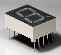
If we look at one digit we can see 10pins each segment and the small dot are LED�s, each of them has one terminal connected to a common pin, from
this comes the name common anode or common cathode, and the other terminal is connected to a standalone pin, since the common pin is doubled, we
have the 10 pins for each digit.
Lets take as example the common anode type, to light the segments we need to connect the positive supply rail to the common pin, and pull to ground
the segments, each segment depending on its size can handle a few miliamps, after all we are talking about LED�s not bulbs. That�s fine if you need
just one number to display, but how can these digits be connected to form a multi-digit display? The first approach is to connect each segment to a
micro-controller pin, this way for each digit you need 8 pins and isn�t elegant at all.
The other solution is to connect each corresponding segment from the digits to a common bus, and power the digits one at a time, thus multiplexing
the data.
Concept and visual structure:
The individual segments of a seven-segment display.A seven segment display, as its name indicates, is composed of seven elements. Individually on or
off, they can be combined to produce simplified representations of the arabic numerals. Often the seven segments are arranged in an oblique (slanted)
arrangement, which aids readability. In most applications, the seven segments are of nearly uniform shape and size (usually elongated hexagons, though
trapezoids and rectangles can also be used), though in the case of adding machines, the vertical segments are longer and more oddly shaped at the ends
in an effort to further enhance readability.
Each of the numbers 0, 6, 7 and 9 may be represented by two or more different glyphs on seven-segment displays.
LED-based 7-segment display showing the 16 hex digits.The seven segments are arranged as a rectangle of two vertical segments on each side with one
horizontal segment on the top, middle, and bottom. Additionally, the seventh segment bisects the rectangle horizontally. There are also
fourteen-segment displays and sixteen-segment displays (for full alphanumerics); however, these have mostly been replaced by dot-matrix displays.
The segments of a 7-segment display are referred to by the letters A to G, as shown to the right, where the optional DP decimal point (an "eighth
segment") is used for the display of non-integer numbers.
The animation to the left cycles through the common glyphs of the ten decimal numerals and the six hexadecimal "letter digits" (A�F). It is an image
sequence of a "LED" display, which is described technology-wise in the following section. Notice the variation between uppercase and lowercase letters
for A�F; this is done to obtain a unique, unambiguous shape for each letter (otherwise, a capital D would look identical to an 0 (or less likely O)
and a capital B would look identical to an 8).
Seven segments are, effectively, the fewest required to represent each of the ten Hindu-Arabic numerals with a distinct and recognizable glyph.
Bloggers have experimented with six-segment and even five-segment displays with such novel shapes as curves, angular blocks and serifs for segments;
however, these often require complicated and/or non-uniform shapes and sometimes create unrecognizable glyphs.[1]
Implementations:
An incandescent light type early seven-segment display.
A mechanical seven-segment display for displaying automotive fuel prices.Seven-segment displays may use a liquid crystal display (LCD), arrays of
light-emitting diodes (LEDs), or other light-generating or controlling techniques such as cold cathode gas discharge, vacuum fluorescent, incandescent
filaments, and others. For gasoline price totems and other large signs, vane displays made up of electromagnetically flipped light-reflecting segments
(or "vanes") are still commonly used. An alternative to the 7-segment display in the 1950s through the 1970s was the cold-cathode, neon-lamp-like
nixie tube. Starting in 1970, RCA sold a display device known as the Numitron that used incandescent filaments arranged into a seven-segment display.[2]
In a simple LED package, typically all of the cathodes (negative terminals) or all of the anodes (positive terminals) of the segment LEDs are
connected together and brought out to a common pin; this is referred to as a "common cathode" or "common anode" device. Hence a 7 segment plus decimal
point package will only require nine pins (though commercial products typically contain more pins, and/or spaces where pins would go, in order to
match industry standard pinouts).
Integrated displays also exist, with single or multiple digits. Some of these integrated displays incorporate their own internal decoder, though most
do not � each individual LED is brought out to a connecting pin as described. Multiple-digit LED displays as used in pocket calculators and similar
devices used multiplexed displays to reduce the number of IC pins required to control the display. For example, all the anodes of the A segments of
each digit position would be connected together and to a driver pin, while the cathodes of all segments for each digit would be connected. To operate
any particular segment of any digit, the controlling integrated circuit would turn on the cathode driver for the selected digit, and the anode drivers
for the desired segments; then after a short blanking interval the next digit would be selected and new segments lit, in a sequential fashion. In this
manner an eight digit display with seven segments and a decimal point would require only 8 cathode drivers and 8 anode drivers, instead of sixty-four
drivers and IC pins. Often in pocket calculators the digit drive lines would be used to scan the keyboard as well, providing further savings; however,
pressing multiple keys at once would produce odd results on the multiplexed display.
For many applications, dot-matrix LCDs have largely superseded LED displays, though even in LCDs 7-segment displays are very common. Unlike LEDs, the
shapes of elements in an LCD panel are arbitrary since they are formed on the display by a kind of printing process. In contrast, the shapes of LED
segments tend to be simple rectangles, reflecting the fact that they have to be physically moulded to shape, which makes it difficult to form more
complex shapes than the segments of 7-segment displays. However, the high common recognition factor of 7-segment displays, and the comparatively high
visual contrast obtained by such displays relative to dot-matrix digits, makes seven-segment multiple-digit LCD screens very common on basic
calculators.
 Alphabetic display:
Main article: Seven-segment display character representations
In addition to the ten numerals, seven segment displays can be used to show letters of the latin, cyrillic and greek alphabets including punctuation,
but only few representations are unambiguous and intuitive at the same time. It is possible to represent hexadecimal unambiguously by using a mixture
of letter cases (AbCdEF is typical) and using a representation of 6 that has the top segment illuminated. This is frequently used to output
hexadecimal codes for troubleshooting purposes. Short messages giving status information (e.g. "no disc" on a CD player) are also commonly represented
on 7-segment displays. In the case of such messages it is not necessary for every letter to be unambiguous, merely for the words as a whole to be
readable.
Similar displays with fourteen or sixteen segments are available allowing decent representations of the alphabet.
Using a restricted range of letters that look like (upside-down) digits, seven-segment displays are commonly used by school children to form words
and phrases using a technique known as "calculator spelling".
Numbers to 7-segment-code:
A single byte can encode the full state of a 7-segment-display. The most popular bit encodings are gfedcba and abcdefg - both usually assume 0 is off
and 1 is on.
This table gives the hexadecimal encodings for displaying the digits 0 to 9:
| Digit |
gfedcba |
abcdefg |
a |
b |
c |
d |
e |
f |
g |
| 0 |
0x3F |
0x7E |
on |
on |
on |
on |
on |
on |
off |
| 1 |
0x06 |
0x30 |
off |
on |
on |
off |
off |
off |
off |
| 2 |
0x5B |
0x6D |
on |
on |
off |
on |
on |
off |
on |
| 3 |
0x4F |
0x79 |
on |
on |
on |
on |
off |
off |
on |
| 4 |
0x66 |
0x33 |
off |
on |
on |
off |
off |
on |
on |
| 5 |
0x6D |
0x5B |
on |
off |
on |
on |
off |
on |
on |
| 6 |
0x7D |
0x5F |
on |
off |
on |
on |
on |
on |
on |
| 7 |
0x07 |
0x70 |
on |
on |
on |
off |
off |
off |
off |
| 8 |
0x7F |
0x7F |
on |
on |
on |
on |
on |
on |
on |
| 9 |
0x6F |
0x7B |
on |
on |
on |
on |
off |
on |
on |
Suggested Reading:
The Led Light
Electronics Tutorials
Wikipedia, Light Emitting Diode
Copyright and Credits:
Editor, © Tony van Roon, graphics and photos, newly edited material, October 2010.
MC4511 explanation, © Ken Bigelow, http://www.play-hookey.com/digital/experiments/seven_seg_driver.html.
(Hugo) Gernsback Publishing is (sadly) out of business since 2000.
Re-posting or taking graphics in any way or form from this website or of this project is expressly prohibited by
international copyright © laws. Permission by written permission only.
Copyright © 2010 - Tony van Roon, VA3AVR
Last updated: December 15, 2010