Diode Data
"The characteristics, codes, data, encapsulations and various formulas relating to diodes, thyristors,
triacs, and LEDs."
© by Mike Tooley, Tony van Roon
Diodes and Diode Data
A diode, or "rectifier," is any device through which electricity can flow in only one direction. The first diodes were crystals used as
rectifiers in home radio kits. A weak radio signal was fed into the crystal through a very fine wire called a cat's whisker. The crystal
removed the high frequency radio carrier signal, allowing the part of the signal with the audio information to come through loud and clear.
The crystal was filled with impurities, making some sections more resistant to electrical flow than others. Using the radio required
positioning the cat's whiskers over the right kind of impurity to get electricity to flow through the crystal to the output below it.
At the time, though, no one really understood about the impurities -- then in 1939 Russell Ohl accidentally discovered that it was the boundary
between sections of different purity that made the crystal work. Now that the way they work is understood, manufacturers make crystal diodes
that work much more consistently than the ones in those original radio kits.
 A crystal diode is made of two different types of semiconductors right next to each other. One side is easy for electrons to travel through;
one side is much tougher. It's something like trying to swim through a pool filled with water and then a pool filled with mud: swimming through
water is easy; swimming through mud is next to impossible. To an electron some semiconductors seem like water, some like mud.
A crystal diode is made of two different types of semiconductors right next to each other. One side is easy for electrons to travel through;
one side is much tougher. It's something like trying to swim through a pool filled with water and then a pool filled with mud: swimming through
water is easy; swimming through mud is next to impossible. To an electron some semiconductors seem like water, some like mud.
One side of the semiconductor boundary is like mud, one like water. If you try to get electricity to move from the mud side to the water side,
there's no problem. The electrons just jump across the boundary, forming a current. But try to make electricity go the other way and nothing
will happen. Electrons that didn't have to work hard to travel around the water side just don't have enough energy to make it into the mud
side. (In real life, there are always a few electrons that can trickle in the wrong direction, but not enough to make a big difference.)
This boundary has turned out to be crucial for our daily lives. Diodes change the alternating current that comes from your wall outlet into the
direct current that most appliances need. And transistors need two such boundaries to work.
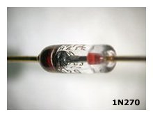
 Semiconductor diodes are generally a single p-n junction of either Silicon(Si) or Germanium (Ge), although Germanium diodes are seldom used these
days. In order to maintain conduction, the p-type material (the p-type connection constitutes the anode while the n-type connection constitutes
the cathode). The direction of current flow is from anode to cathode whom the diode is conducting, as shown in Fig. 1.
Very little current (negligible in the case of the most silicon devices) flows in the reverse direction Fig. 2.
Semiconductor diodes are generally a single p-n junction of either Silicon(Si) or Germanium (Ge), although Germanium diodes are seldom used these
days. In order to maintain conduction, the p-type material (the p-type connection constitutes the anode while the n-type connection constitutes
the cathode). The direction of current flow is from anode to cathode whom the diode is conducting, as shown in Fig. 1.
Very little current (negligible in the case of the most silicon devices) flows in the reverse direction Fig. 2.
Diodes exhibit a low resistance to current flow in one direction and a high resistance to current flow in the other. The direction in which the
current flows is referred to as the forward direction while that in which negligible current flows is known as the reverse direction. When a diode
is conducting, a diode is said to be forward biased and a small voltage (ideally zero) is dropped across it. This voltage is know as the forward
voltage drop. The maximum reverse voltage (Vrrm) or peak inverse voltage (PIV).
 Germanium diodes conduct at lower forward voltages than their silicon counterparts, but they tend to exhibit considerable more reverse leakage current.
Hence the fact that they are seldom used anymore.
Germanium diodes conduct at lower forward voltages than their silicon counterparts, but they tend to exhibit considerable more reverse leakage current.
Hence the fact that they are seldom used anymore.
One of the applications they still find a use is battery chargers for 6/12/24V Lead-Acid batteries.
The leakage current to charge those heavy-duty batteries seem not to matter much.
Furthermore, the forward resistance of a conducting silicon diode is much lower than that of a comparable germanium type.
Hence, again, germanium diodes are used primarily for signal detection purposes whereas silicon devices are uses for rectification and for general
purpose applications.
Typical forward and reverse characteristics for comparable germanium and silicon diodes are shown in Fig. 3.
Diodes are often divided into signal and rectifier types, according to their principal field of application. Signal diodes require consistent
forward characteristics with low forward voltage drop.
Rectifier diodes need to be able to cope with high values of reverse voltage and large values of forward current, consistency of characteristics is of
secondary importance in such applications.
Rectifier diodes are often available in the form of a Bridge (see Fig. 4) which provides fullwave rectification.
Various diode encapsulations are illustrated in Fig. 5
Diode Coding
The European system for classifying semiconductor diodes involves an alphanumeric code which employs either two letters and three figures (general
 purpose diodes) or three letters and two figures (special purpose diodes). The first two letters have the following significance:
   First Letter - semiconductor material:
         A  Germanium
         B  Silicon
         C  Gallium Arsenide, etc.
         D  Photo diodes, etc.

   Second Letter - application:
         A  General Purpose
         B  Tuning (varicap) Diode
         E  Tunnel Diode
         P  Photovoltaic Diode
         Q  Light Emitting Diode (LED)
         T  Controlled Rectifier
         X  Varactor Diode
         Y  Power Rectifier
         Z  Zener Diode
 In the case of diodes for specialized applications, the third letter does not generally have any particular significance.
Zener diodes have an additional letter (which appears after the numbers) which denotes the tolerance of the zener voltage.
The following letters are used:
         A  1%         C  5%
         B  2%         D  10%
Zener diodes also have additional characters which indicate the zener voltage (e.g. 9V1 denotes 9.1V).
  Example 1
     Identify each of the following diodes:
       (i) AA113
      (ii) BB105
     (iii) BZY88C4V7
    Diode (i) is a general purpose germanium diode.
    Diode (ii) is a silicon diode for tuning applications (sometimes referred
          to as a 'varicap'.
    Diode (iii) is a silicon zener diode having 5% tolerance and 4.7V zener voltage
Diode Data:
The following tables summarize the characteristics of a variety of popular semiconductor diodes.
Note: Most of the bridge rectifiers listed are available in 200V, 400V and 600V versions. It is important to ensure that manufacturers' voltage
ratings are not exceeded.
Hints and Tips:
When designing power supply circuits (in which appreciable currents are present) it is important to allow for the forward voltage drop associated with
each rectifier diode. In a bridge rectifier, for example, two diodes will conducting any one time. The total forward voltage drop associated with
these diodes can approach 2V and this should be allowed for when determining the AC input voltage to the rectifier.
The reverse leakage current of a diode increases markedly as the junction temperature increases. This results in a reduction in overall efficiency
ratio of forward current to reverse current) at high temperatures.
Operating a diode a, or beyond, the stated limits for Vrrm or PIV will result in a high risk of breakdown. Since rectifier failure can have
disastrous consequences, it is always advisable to operate diodes well within the stated limits (to ensure safety, a 100% margin should be allowed).
Schottky diodes exhibit a forward voltage drop which is approximately half that of conventional silicon diodes coupled with very fast reverse
recovery. Schottky diodes are preferred in switching applications (e.g. switched mode power supplies) where very low forward voltage drop and fast
switching is a prime consideration.
 Zener Diodes:
Zener diodes are silicon diodes which are specially designed to exhibit consistent reverse breakdown characteristics. Zener diodes are available in
various families (according to their general characteristics, encapsulation(casing) and power ratings) with reverse breakdown (zener) voltages in
the E12 and E24 series (ranging from 2.4V to 91V).
A typical characteristic for a 5.1V zener diode is shown in Fig. 6. The following series of zener diodes are commonly
available:
   BZX88 series:
   Miniature glass encapsulated diodes rated at 500mW (at 25 °C).  Zener
   voltages range from 2.7V to 15V (voltages are quoted for 5mA reverse current
   at 25 °C.

   BZX55 series:
   Low-power diodes rated at 500mW and offering zener voltages in the range of
   2.4V to 91V.

   BZX61 series:
   Encapsulated alloy junction rated at 1.3Watt (25 °C ambient).  Zener
   voltages range from 7.5V to 72V.

   BZX85 series:
   Medium-power glass-encapsulated diodes rated at 1.3Watt and offering zener
   voltages in the range of 5.1V to 62V.

   BZX93 series:
   High power diodes in stud mounting encapsulation.  Rated at 200Watt for
   ambient temperatures up to 75 °C.  Zener voltages range from 9.1V to 75V.

	 BZX97 series:
   Medium power wire-ended diodes rated at 1.5W and offering zener voltages in
   the range of 9.1V to 37V.

   1N5333 series:
   Plastic encapsulated diodes rated at 5W. Zener Voltages range from 3.3V to
   24V.
 Zener diodes are generally plastic or glass encapsulated in the same manner as conventional silicon diodes. As with conventional silicon diodes, the
cathode connection is marked with a stripe Fig. 7.
Zener diodes are generally plastic or glass encapsulated in the same manner as conventional silicon diodes. As with conventional silicon diodes, the
cathode connection is marked with a stripe Fig. 7.
The slope resistance of a zener diode is the rate of change of reverse voltage (zener voltage) with diode current. Slope resistance is measured in
the breakdown region and expressed in ohms. An ideal zener diode would have zero slope resistance (i.e. the diode would conduct perfectly at its
rated zener voltage). In practice, values of 200 or less can be achieved.
The temperature coefficient of zener voltage is the change of zener voltage (from its rated value) which results from a temperature change of 1°C.
Temperature coefficient (which should ideally be zero) is expressed in mV/deg.C. In many voltage reference applications, it is essential for the
reference diode to exhibit a zener voltage which does not vary with temperature. The following data (for the BZX55 series) is typical of most low-power
zener diodes.
Example:
A zener diode is to be used as a voltage reference. The diode has the following specifications:
        Zener voltage (at 20 °C): 9.1V
        Temperature coefficient: +4mV/°C
If the equipment is designed to operate over the range -10°C to +40°C, determine the extreme values of reference voltage and the percentage
change in the reference voltage over the working range. The temperature coefficient is positive and thus the zener voltage will increase with
temperature.
At 40°C the zener voltage will be given by:
Vz = 9.1V + ((40 - 20) x 4 mV) = 9.1V + 80mV = 9.18V
At -10°C the zener voltage is:
Vz = 9.1V - ((20-10) x 4 mV) = 8.98V
 Hints and Tips:
Zener diodes may be connected in series to obtain higher voltages. As an example, a 15.9V reference can be produced by connecting a 6.8V zener
diode in series with a 9.1V zener diode.
Care must taken to ensure that zener diodes operate within their rated power dissipation.
Zener diodes generally perform best when rated at voltages of between 5V and 6V. Hence, in order to obtain optimum performance (in terms of both
slope resistance and temperature coefficient) reference voltage sources based upon zener diodes should utilize components which have zener voltages of
between 5.1V and 6.2V where necessary, external circuitry can be used to provide voltage amplification.
Zener diodes can generate a significant amount of noise and, in significant voltage gain (e.g. the stabilization of an amplifier bias supply) it
is essential to provide adequate decoupling. A parallel connected capacitor of between 1uF and 100uF will provide effective in most applications.
Thyristors:
Thyristors, (or silicon controlled rectifiers) are three-terminal devices which can be used for switching and AC power control. Thyristors can switch
very rapidly from a non-conducting state to a conducting state. In the off-state, the thyristor exhibits negligible leakage current while, in the
on-state the device exhibits very low resistance. This results in very little power loss within the thyristor even when appreciable power levels are
being controlled. Once switched into the conducting state, the thyristor will remain conducting (e.i. is latched in the on-state) until the forward
currents is removed from the device. In DC applications this necessitates the interruption (or disconnection) of the supply before the device can
be reset into its nonconducting state. Where the device is used with an alternating supply, the device will automatically become reset whenever the
main supply reverses. The device can then be triggered on the next half-cycle having correct polarity to permit conduction. Like their conventional
silicon diode counter parts, thyristors have anode and cathode connections; control is applied by means of gate terminal Fig. 8.
The device is triggered into the conducting (on-state) by means of the application of a current pulse to this material.
Thyristor Data:
The table on the left summarizes the characteristics of a variety of popular thyristors.
Hints and Tips:
Wherever possible, thyristor trigger pulses should have the fastest possible rise times. Signals with slow rise times or poorly defined edges are
generally unsatisfactory for triggering purposes.
Sufficient gate current must be made available in order to ensure effective
triggering.
Thyristors will turn on faster (and power dissipation within the device will be minimized) as gate current is increased.
Care should, however, be taken to ensure that the peak value of gate does not exceed the rated value for the device.
The pulse width of the trigger pulse applied to the gate of a thyristor must be kept short in order to minimize gate power dissipation.
In order to obtain an adequate range of control in AC power control applications, the thyristor triggering device should be designed so that it
will proved effective triggering over a sufficiently wide angle of the applied AC voltage. Failure to observe this rule will
result in a limited range of control.
 Triacs:
Triacs are a refinement of the thyristor which, when triggered, conduct on both positive and negative half-cycles of the applied voltage. Triacs have
three terminals known as the main terminal one (MT1), main terminal two (MT2), and the gate (G) as shown in Fig. 10.
Triacs can be triggered by both positive and negative voltages present at the gate. Triacs thus provide full-wave control and offer superior
performance in AC power control applications when compared with thyristors which only provide half-wave control. In order to simplify the design of
triggering circuits, triacs are often used in conjunction with diacs (equivalent to a bi-directional zener diode). A typical diac conducts heavily
when the applied voltage exceeds approximately +/- 32V. Once in the conducting state, the resistance of the diac falls to a very low value and thus
a large value current will flow. The characteristic of a typical diac is shown in Fig. 11.
 Triac Data:
The following table summarizes the characteristics of a variety of popular triacs.
Hints and Tips:
Thyristors and triacs switch on an off very rapidly. In AC power control applications, this rapid switching can result in transients which may be
conveyed some distance via the AC mains wiring. To minimize such effects and prevent radiation of noise, an L-C filter should be fitted in close
proximity to the power control device, as shown in Fig. 13.
Leds:
Light Emitting Diodes (LEDs) can be used as general purpose indicators and, compared with conventional filament lamps, operate from significantly
smaller voltages and currents. LEDs are also very much more reliable than filament lamps. Most regular LEDs will provide a reasonable level of light
output when a forward current of between 5mA and 20mA is applied.
Light Emitting Diodes are available in various formats, with the round types being most popular. Round LEDs are commonly available in the 3mm and 5mm
(0.2 inch) diameter plastic packages (see Fig. 14 and also in 5mm x 2mm rectangular format. The viewing angle for round
LEDs tends to be in the region of 20° to 40° whereas for rectangular types this is increased to around 100°. The last couple years we have
seen other formats as well like the 1mm and 10mm types. More of those details are mentioned in the LED tutorial.
In order to limit the forward current to an appropriate value, it is usually necessary to include a fixed resistor in series with a LED indicator. The
value of the resistor may be calculated from:
R = (V - Vf) / I
where Vf is the forward voltage drop produced by the LED and V is applied voltage. It is usually safe to assume that Vf will be 2V and choose the
nearest preferred value for R.
Example 3
An LED is to be used to indicate the presence of 21V DC supply rail. If the LED has a nominal forward voltage of 2.2V, and its rated at a current of
15mA determine the value of the required series resistor.
Here we can use the formula:
R = (V - Vf) / I = (21 - 2.2V) / .015 = 1.25K
The nearest standard value is 1K2 or 1200 ohm. The power dissipated in the resistor will be 0.015 times 18.8V, or 280mW.
 Hints and Tips:
Avoid inadvertent reverse LED connection. Reverse voltages in excess of about 5V will cause permanent damage.
For battery power equipment (particularly where a number of LED indicators are used) minimal values of forward current should be employed in order
to ensure long battery life.
A forward current of 5mA (per LED) will be perfectly adequate in many applications. This is of course for the standard low light LED types.
The high- and ultra-bright types may goes as much as 18mA.
Where there are several LEDs are to be used together, they should be connected in series (and not parallel) in order to ensure equal levels of
light output.
Yellow and Green LED generally give less output (for a given forward current) than their standard red counterparts. To maintain an equal light
output when several LEDs of different colors are used together, different values of series resistors may be employed. As a rule of thumb, series
resistors for yellow and green LEDs should be chosen so that they are 10% to 15% lower in value than those used with red diodes (care should, however,
be taken to ensure that operating currents are still within the manufacturer's specified upper limit.
In applications involving low AC voltages, a conventional low-current silicon diode (e.g. 1N4148) can be wired in parallel with a LED to provide a
simple AC indicator.
Suggested Reading:
- "The Way Things Work", by David Macaulay
- "Physics for Scientists and Engineers", by Paul Fishbane, Stephen Gasiorowicz, and Stephen Thornton
- "Feynman's Lectures on Physics", by Richard Feynman
Copyright and Credits:
Mike Tooley, "Diode Data", ET&T May 1990.
Tony van Roon, editor, graphics and photos, new material, September 2010.
(Hugo) Gernsback Publishing is (sadly) out of business since January 2000.
Re-posting or taking graphics in any way or form from this website or of this project is expressly prohibited by
international copyright © laws. Permission by written permission only.
Copyright © 2010 - Tony van Roon, VA3AVR
Last updated: November 18, 2010