Transistors Tutorial
Part 5:
by Tony van Roon (VA3AVR)
"Learn about the audio amplifiers in stereos, tuners, tape/cassette, and CD
players, and apply your knowledge to experiments or designs."
Transistors are the key components in many different kinds of audio preamplifiers, amplifiers, and tone-control
circuits. Recent articles in this series have discussed the operation principles and applications for discrete
bipolar junction transistors (BJT). Earlier articles have covered such subjects as low-power amplifier circuits,
multivibrators, and oscillators.
 Audio Amplifier Basics:
A modern stereo amplifier system has two closely matched high-fidelity audio amplifier channels. Typically each of
those channels offers switch-selectable inputs for such signal sources as a tuner, tape-player, CD-player, TV, MTS,
etc. Each also provides a single output signal to a high-power loudspeaker. To analyze one of those systems, it is
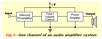
useful to divide the system into three functional circuit blocks, as shown in Fig. 1.
 The first of these blocks is the selector/preamplifier. It permits the system listener to select the desired input
signal source, and it automatically applies an appropriate amplification level and frequency correction to the signal
to condition it for the second circuit block, tone/volume control.
The first of these blocks is the selector/preamplifier. It permits the system listener to select the desired input
signal source, and it automatically applies an appropriate amplification level and frequency correction to the signal
to condition it for the second circuit block, tone/volume control.
The tone/volume-control block permits the listener to adjust the frequency characteristics and the amplitude of the
audible output to suit his individual taste. This block might also contain additional filter circuits including one
specifically designed to screen out scratch and rumble.
The last section of the amplifier system is the power amplifier. It might be able to produce power levels from a few
hundred milliwatts to hundreds of watts. Audio power amplifiers are designed to cover the audio frequency range with
minimal distortion. Most quality products today include automatic overload and thermal-runaway protection.
The three sections of the audio amplifier system are all powered from a single built-in power supply. All three
sections include individual power supply decoupling networks to prevent unwanted signal interference. The first two
amplifier blocks will be discussed here.
 Simple Preamplifiers:
The audio preamplifier circuit modifies the signal characteristics so that it will have a steady frequency response
and the nominal 100-millivolt output amplitude necessary for driving the tone/volume control section.
If the input signal is derived from a radio tuner or a tape player, the signal characteristics are usually in a form
that can be fed directly to the tone/control section, bypassing the preamplifier. However, if the input is obtained
from a micro-phone or other audio input device, it will probably need preamplifier conditioning.
Two basic kinds of transducers are found in micro-phones and audio pickups: magnetic or piezoelectric ceramic/crystal.
Magnetic transducers typically offer low output impedance and a low signal sensitivity of about 2 millivolts.
Their outputs must be fed to a high-impedance preamplifier stage with near-unity voltage gain.
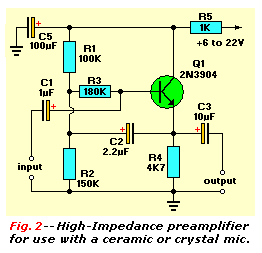
 Most microphones have a near flat frequency response, so they can be matched to simple, flat-response preamplifier
stages. Figure 2 shows a unity-gain preamplifier circuit that will work with most
high-impedance ceramic or crystal microphones. It is an emitter-follower (common-collector) amplifier with an input
network bootstrapped by C2 and R3. It has a typical input impedance of about 2 megohms. The combination of C5 and R5
decouples the amplifier from the DC power supply.
Most microphones have a near flat frequency response, so they can be matched to simple, flat-response preamplifier
stages. Figure 2 shows a unity-gain preamplifier circuit that will work with most
high-impedance ceramic or crystal microphones. It is an emitter-follower (common-collector) amplifier with an input
network bootstrapped by C2 and R3. It has a typical input impedance of about 2 megohms. The combination of C5 and R5
decouples the amplifier from the DC power supply.
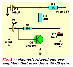
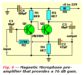
Figures 3 and 4 show alternative preamplifier circuits that will match magnetic microphones. The single-stage circuit
of Fig. 3 gives 46dB (x200) of voltage gain, and will work with most magnetic microphones.
The two-stage circuit of Fig. 4, however, gives 76dB of voltage gain, and it is intended
for preamplification of the output of very-low-sensitivity magnetic microphones.
RIAA Preamplifier Circuits:
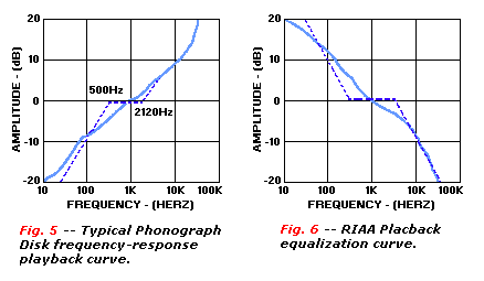
The replay of a constant-amplitude 20Hz to 20KHz variable-frequency signal that has been recorded on a phonograph disc
with conventional stereo recording equipment will generate the nonlinear frequency response curve shown in Fig. 5.
Here, the dotted line shows the idealized shape of this curve, and the solid line shows an actual shape.
Examination of the idealized (dotted) version of the curve in Fig. 5 will show that the response is flat between 500
and 2120 Hz. However, it rises at a rate of 6dB/octave (20 dB/decade above 2120 Hz), and falls at a 6dB/octave rate
between 500 Hz and 50 Hz. The response then flattens at frequencies below 50Hz.
There are good--but difficult to explain--reasons why the precise Fig. 5 recording curves are used. However, all you
really need to know is that they make it possible to produce disc recordings with excellent signal-to-noise ratios and
wide dynamic ranges. The curves were applied during record pressing.
The important point to be made here is that when a disc is replayed, the output of the pickup device must be passed to
the power amplifier through a preamplifier whose frequency equalization curve is the mirror image (exact inverse) of
the one used to make the original recording. As a result, a linear overall record-to-replay response is obtained.
Figure 6 shows the RIAA equalization curve. RIAA is an abbreviation for the
Recording Industry Association of America, the organization that standardized the precise
specification of the curve for the equalization of phonograph records. When long-playing phonograph (record-player)
records were the primary source of recorded music and audio entertainment, circuit designers had to include filter
networks that corrected the input from the record to conform to the RIAA equalization curve.
 The relatively recent(1994) world-wide conversion to compact discs (CDs) as the primary source of recorded music and
entertainment has diminished the importance of the RIAA curve. Equalization is not required for linear signal sources
such as CDs.
The relatively recent(1994) world-wide conversion to compact discs (CDs) as the primary source of recorded music and
entertainment has diminished the importance of the RIAA curve. Equalization is not required for linear signal sources
such as CDs.
Nevertheless, a preamplifier with an RIAA equalization network is still needed if you want to play any of the pressed
long-playing and 45 rpm records. This equalization can be obtained by wiring frequency-dependent, resistive capacitive
feedback networks into a preamplifier. This circuitry causes the gain to fall as the frequency rises. One network
will control the 50 to 500 Hz response, and the other will control the 2120 Hz to 20 kHz response.
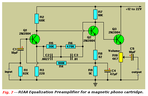
Figure 7 is the schematic for an amplifier with those networks that will work with any
magnetic phono cartridge. It gives a 1-volt output from a 6-millivolt input at 1KHz, and provides equalization that
is within 1 dB of the RIAA standard between 40 Hz and 12KHz.
 The preamplifier circuit is designed around transistors Q1 and Q2, with C2 and R5, and C3 and R6 forming the feedback
resistor capacitor equalization network. The output of the emitter-follower buffer stage, transistor Q3, can be
controlled by volume control potentiometer R10.
The preamplifier circuit is designed around transistors Q1 and Q2, with C2 and R5, and C3 and R6 forming the feedback
resistor capacitor equalization network. The output of the emitter-follower buffer stage, transistor Q3, can be
controlled by volume control potentiometer R10.
The quality of reproduction of ceramic or crystal phono cartridges is generally lower than that of magnetic cartridges,
but they produce far higher amplitude output signals. Ceramic and crystal phone cartridges will work with simple
equalization preamplifiers--one reason why those cartridges were installed in so many low-cost record players.
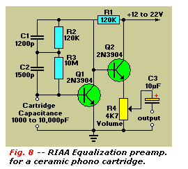
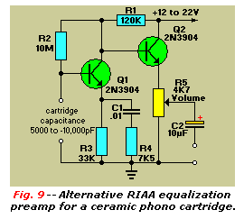
Figure 8 and 9 show alternative phone cartridge preamplifier/equalization circuits that
can function with wither ceramic or crystal phono cartridges. Both circuits are designed around transistorized
emitter-follower output stages Q1 and Q2. The output of the circuit in Fig. 8 can be
controlled by volume control potentiometer R4, and that of Fig. 9 is controlled by R5.
The preamplifier/equalizer in Fig. 8 will work with any phone cartridge whose capacitance is between 1000 and 10,000pF.
Two-stage equalization is provided by the resistance-capacitance network made up of C1, C2, R2, and R3.
Preamplification/equalization for this circuit is typically within 1.6 dB of the RIAA standard between 40 Hz and 12KHz.
The alternative preamplifier/equalizer shown in Fig. 9 will work only with phono cartridges whose capacitance value
are between 5000 and 10,000pF because this capacitance is part of the circuit's frequency response network. The
other part of the network is formed by C1 and R3. At 50 Hz, this circuit has a high input impedance of about 600
kilohms, which causes only slight cartridge loading. However, as frequency increases, input impedance decreases
sharply, increasing cartridge loading and effectively reducing circuit gain. The equalization curve approximates the
RIAA standard, and circuit performance is adequate for most practical applications.
 A Universal Preamplifier:
Most audio amplifier systems must have preamplifiers with many different characteristics. These include high-gain
linear response for magnetic microphones, low-gain linear response for tuners, and high-gain RIAA equalization for
magnetic phone cartridges.
To meet this broad requirement, most amplifier designers include a single universal preamplifier circuit such as the
one shown in Fig. 10. Basically a high-gain linear amplifier, its characteristics can be
altered by switching alternative resistor filter networks into its feedback system.
For example, when the selector switch is set to the Mag phono position, alternative input sources can be
selected by S1-a, and appropriate linear-response gain control feedback resistors R8, R9, and R10 are now selected by
S1-b. Those feedback resistor values are selected between 10 kilo ohms and 10 megohms to suit individual listener
tastes. Circuit gain will be proportional, to the feedback resistor value.
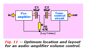
Volume Control:
The Volume control circuitry of an audio amplifier system is normally located between the output of the
preamplifier stage and the input of the tone-control circuit. It is usually only a potentiometer within the circuit,
as shown in Figs. 7, 8, and 9. However, the catch here is that rapid rotation of the potentiometer knob can apply DC
voltage to the next circuit for brief intervals. That voltage could upset circuit bias and cause severe signal
distortion.
The block diagram in Fig. 11 shows the ideal topology and location for a volume control.
It is fully DC-isolated from the output of the preamplifier by capacitor C1, and from the input of the tone-control
circuit by C2. As a result, variation of the wiper of control potentiometer R1 has no effect on the DC bias levels of
either circuit. Potentiometer R1 should have a logarithmic taper, that is, its output should be logarithmic function
rather than linear.
 Passive Tone Control:
A tone-control network permits the listener to change th system amplifier's frequency response to suit his own mood or
taste. He can, for example, boost or reduce the low-frequency (treble) sections of a musical selection to emphasize
the sounds of specific sections of the orchestra.
Tone-control networks typically consists of simple resistive-capacitive filters through which the signals are passed.
Because these networks are passive, they cause some signal attenuation. Tone control networks can, if desired, be
wired into the the feedback loops of simple transistor amplifiers to give the system an overall signal gain. Those are
known as active tone control circuits.
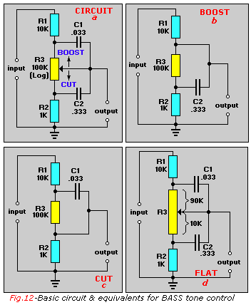
Fig. 12-a shows a typical passive bass tone-control network, and
Fig. 12-b through Fig. 12-d show the equivalent of this
circuit when control potentiometer R3 is set to its maximum boost, maximum cut, and flat
positions, respectively. Capacitors C1 and C2 are effectively open circuited when the frequency is at its lowest bass
value. It can be seen from Fig. 12-b that the boost circuit is equivalent to a voltage divider formed by dividing
10 kilohms by 101 kilohms. This arrangement results in a low resistive value of about 100 ohms that only slightly
attenuates bass signals.
The Fig. 12-c cut circuit, by contrast, has a voltage divider equal to 100 kilohms divided by a 1 kilohm which
gives a signal attenuation of about 40 dB. Finally, in Fig. 12-d when potentiometer R3 is set to the flat
position, it will have 90 kilohms of resistance above the wiper and 10 kilohms below it.
This circuit resistance value is equal to 100 kilohms divided by 11 kilohms.
It gives a signal attenuation of about 20 dB at all frequencies. As a result, the circuit gives a maximum bass boost
of about 20 dB or cut relative to the flat signals.
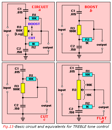
Fig. 13 shows a typical passive treble tone-control network together with its
equivalent circuits under maximum boost, maximum cut, and flat operating conditions. This circuit
also provides about 20 dB of signal attenuation when potentiometer R3 is in the flat position, and it gives
maximum treble boost or cut values of about 20 dB relative to its flat performance.
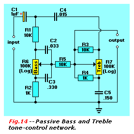 Finally, Fig. 14 shows how the Fig. 12-a and 13-a schematics can be combined to make a
complete bass and treble tone-control network The 10-kilohm resistor R5 has been added to minimize unwanted interaction
between the two connected circuit sections. The input to this network can be taken from the circuit's volume control,
and its output can be fed to the input of the power amplifier.
Finally, Fig. 14 shows how the Fig. 12-a and 13-a schematics can be combined to make a
complete bass and treble tone-control network The 10-kilohm resistor R5 has been added to minimize unwanted interaction
between the two connected circuit sections. The input to this network can be taken from the circuit's volume control,
and its output can be fed to the input of the power amplifier.
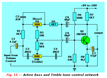
Active Tone Controls:
A tone-control network can be included in the feedback path of a transistor amplifier so that the system will have an
overall signal gain (rather than attenuation) when its controls are in the flat position. These networks can be
simplifier versions of the basic circuit shown in Fig. 14. Fig. 15 is the schematic for
an active tone-control circuit.
A comparison of Figs. 15 and 12 will reveal that the bass control section of Fig. 15 is a simplified version of
Fig. 12-a. It can be seen that the two capacitors C1 and C2 of Fig. 12-a have been replaced by the single 0.039uF
capacitor C2 of Fig. 15. Similarly, the treble version of Fig. 13-a, with resistors R1 and R2 eliminated.
Resistors R3 and R4 balance the performance of the two section of the Fig. 15 control circuit.
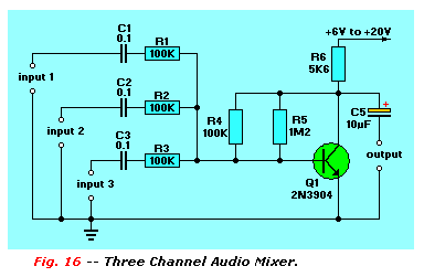
An Audio Mixer:
A multichannel audio mixer is an attractive modification that can be added to the volume/tone-control section of an
audio amplifier. This mixer permits several different audio signals to be mixed together to form a single composite
output signal. This modification will be of value if, for example, you want to hear the front-door buzzer or the
sounds of a baby crying in a child's room while you listening to music.
Figure 16 is the schematic for a three-channel audio mixer that will provide an overall
gain of one between the output and each input channel. Each input channel includes a single 0.1 uF capacitor and a
100-kilohms resistor, to provide an output impedance of 100 kilohms. The number of input channels to this audio mixer
can be increased by adding more capacitors and resistors with the same values as C1 and R1.
The mixer should be located between the output of the tone-control circuitry and the input to the power amplifier.
One input should be taken from the output of the tone-control circuit, and the other inputs should either be grounded
or taken from the desired source.
Continue with Transistor Tutorial Part 6
Copyright © 2006 - Tony van Roon, VA3AVR
Last updated: December 18, 2009