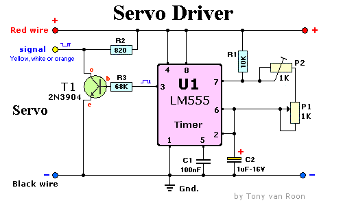
Parts List:
R1 = 10K
R2 = 820 ohm
R3 = 68K
P1 = 1K, potentiometer
P2 = 1K, trim-pot
C1 = 1µF (monolithic)
C2 = 1µF, 16V
Q1 = 2N3904, PN100, NTE123AP, or similar
U1 = LM555, NE555 or MC1455
Additional Notes:
This circuit is just a basic one and can be used to test servos, or as a project interface for other enhancements.
With the above component values, the circuit can drive a servo through a 90-degree rotation. The pulse is 1-mS wide,
plus or minus 0.5 mS. Q1 inverts the signal from the LM555's pin 3. To get a 180-degree
rotation the values of R1, P2, and C1 should be changed to 5K6, 560Ohm and 2uF respectively. R3 accounts for shift
variations in the different variety of servo motors.
Pin 1 = Ground (-)
Pin 2 = Trigger
Pin 3 = Output
Pin 4 = Reset
Pin 5 = Control Voltage
Pin 6 = Threshold
Pin 7 = Discharge
Pin 8 = Vcc (+)

