![[Power Panel]](ppan.gif)
Parts List:
1 large on-on slide switch, double pole
4 Red Jacks
3 Black (blue,or green) Jacks
1 Resistor, 7 Ohms, 10watt minimum, Wire-Wound (for the 6V side of the fuel pump, optional)
1 Knob for the 'Current Adjust' potentiometer
![[Power Panel wiring diagram]](pplayout.gif)
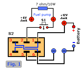
* Note 1:
Cross-wire the 'Fuel
In-Out' switch first before soldering the other wires to it. Pin 1 to pin 4 and pin 3 to pin 6. Use solid,
insulated, wire like bell wire, or bend a thin paperclip in shape and solder that on (see Fig. 4). The two center
contacts (2 & 5) are left open at this time (pin 5 is for negative (-) pump jack, pin 2 is for S1 pushbutton
switch).
Solder also a piece of insulated, solid wire between Pins 2 & 3 of the Potentiometer P1.
Verify S2 to make sure the jumper wires between pins 1/4 and 3/6 are NOT touching each other!
* Note 2: This 'board' refers to the construction of the "Glow-Plug-Driver" itself.
Click here to see: Part 1
o The '+' of the flight box battery goes to the anode of diode D2 (1N5401) of the
Glowplug Driver circuit, and pin 1 of the Fuel In-Out switch S2.
o The '-' of the flight box battery goes to pin 6 of the Fuel-In-Out switch S2 and
pin 5 goes to the fuel pump (-) jack.
o Another red wire from the pump-on/off switch goes to the '+' (red) of the fuel
pump jack (which has one leg of the 7 ohm resistor connected also).
o The 7 ohm/10 watt (wirewound) resistor is mounted between the red +12V and +6V fuel
pump jacks, and is used to reduce the voltage to +6 volt
o Connect a black wire between the glowplug jack (-) and the Emitter of T1 on the
glowplug circuitry.
o Connect the other side of the glowplug jack (+) to the '-' of the the amp-meter.
The positive (+) of the ampmeter goes to the cathode of D2 on the glowplug circuit board, as indicated.
o Connect the red and green wires from the p- and p+ on the glowplug circuit board
to the potentiometer on the power panel. The -p wire goes to the walker (pin 2/3), the +p red wire goes to pin 1 of
the potmeter.
Assembly & Checkout:
o Recheck all wiring and solder connections. No need to destroy your battery or glowplug circuit because of faulty wiring.
o Make sure fuel pump is off. Set the 'glow-adjust' potmeter somewhere in a middle possition.
o Connect the whole assembly to the flight-box battery. No smoke or hot parts anywhere? Continue.
o Check the + jacks for polarity (do they show + something?) Good.
o Next is the fuel pump. Press the on/off switch. Working? If so, leave it on and check the fuel in/out switch. Is the fuel pump
reversing? Good! Hit the on/off switch again to switch it off.
o Glow-adjust potentiometer (P1) in the middle possition? Connect a 6volt, 50mA bulb to the glowplug jacks.
it should start glowing immediately; the amp meter should barely move. If you find that the ampmeter goes in the wrong direction just
switch the wires to the potmeter.
o Vary the potentiometer and check if it effects the brightness a bit. It will vary enough to see that the circuit is operational. Keep in
mind that a bulb does not act the same as a glowplug because of the internal resistance (Ri) when either the bulb or a plug are
glowing. If you don't have a bulb handy use a 1 Ohm/1 Watt resistor (CAUTION: gets hot quickly!). If all seems to work, connect a
glowplug and recheck. Watch the amp meter for this one. Don't go beyond 3 amp or so or you will burn the plug. If you hear a
buzzing sound coming from your circuit, don't be alarmed, this is normal and the way it supposed to be. The sound is coming from
the ampmeter. By the way, the maximum output current seems to be around 4 to 5 amps max depending on the plug. At the field,
when the plug gets wet with fuel, it can draw more amps to keep the plug glowing.
o When everything checks out the panel is ready for flight box installation. I would recommend to insulate the solder side of the
glowplug circuit with something like plastic, tape, heatshrink or even silicon adhesive.

![[Fuel In-Out]](note1.gif)
Final Notes:
The Power-Panel can look very professional. I used rub-on lettering and a couple of (very) thin coats of protective
spray to protect it from scratches and stuff. Too thick a coat of protective spray the first time may make your
rub-on lettering run or produce tiny air bubbles. Covering can also be used successfully and looks also professional.
Have fun with it!
If you only intend to use a 12-Volt fuel pump you can ommit the 6-Volt red jack and the 7 ohm/10 watt resistor. It
can always be added later, at a time convenient for you. However, I don't think it's worth it since the two items
cost only a couple of quarters and I'm working on a Rx field charger which will possibly be connected to this 6volt
jack.
S1 in the prototype is a push on/off button, but basically any switch can be used. The push-on/off switch is
just more convenient. Verify that the switch can handle the current; 1 or 2 amp should be fine.
Back to Glowplug Driver Circuit
Copyright © 1999 Tony van Roon
![[Power Panel]](ppan.gif)
![[Power Panel]](ppan.gif)
![[Power Panel wiring diagram]](pplayout.gif)

![[Fuel In-Out]](note1.gif)