by John Nooyen

Parts List:
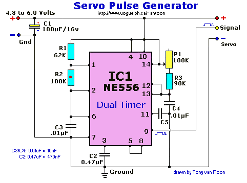
   IC1 = NE556 Dual Timer (or equivalent)        R1 = 62K
    C1 = 100uF/16V (Electrolytic)                R2 = 100K*
    C2 = 0.47uF (ceramic/npo, 470nF)             R3 = 90K
C3,4,5 = 0.01uF (ceramic/npo, 10nF)              P1 = 100k potmeter (linear)
Miscellaneous: Perf board, DC adaptor 6V, ic socket 14pin, case, knob, wire, solder, soldering iron.
The "out" pin(5, 9) is the control or signal wire. For most servos this is either orange, white or yellow.
*John also suggests to try to lower the value of R2 to 100ohms instead of 100K. I would
say experiment with values between a 100 and 2700 ohms and stick with the one that works for you.
Data sheet for the 556 timer is available, just click on NE556 in 'Parts & Description'.
Notes:
This circuit is from John Nooyen's good website (mirrored with permission).
The original drawing had an error and failed to pulse. This is now fixed with a connection from pin 4 & 10 to pin
14 or + 5V.
Apologies for the inconvenience to those with minor experience in electronics. The Servo Pulse Generator is very
handy to judge the servo travel without going through the hookup of the Rx and Transmitter and all the messy wiring.
Back to Gadgets Menu page

