Home » Circuits
Cricket Chirping Generator Circuit Diagram
Funny gadget for props and jokes, 5 - 12V Battery operation
This circuit generates an astonishingly real imitation of the chirping of the cricket. A suitable audio wave form is generated by IC2 and related components, driving the loudspeaker through Q1. To allow a more real-life behavior, the chirp is interrupted in a pseudo-casual way by two timers built around IC1C and IC1D, whose outputs are mixed into IC1B and further time-delayed by IC1A, driving the reset pin of IC2.
An optional Photo resistor can be wired across this pin and positive supply, allowing circuit starting in the dark and stopping when light is coming, thus imitating the cricket's behavior even more closely. R9 acts as volume control and can be a preset trimmer or a small potentiometer.
Circuit diagram:
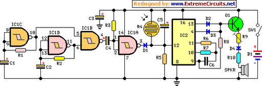
R1_____________330K 1/4W Resistor
R2_____________220K 1/4W Resistor
R3,R6__________100K 1/4W Resistors
R4_____________Photo resistor (Optional, see text)
R5,R7___________22K 1/4W Resistors
R8______________10K 1/4W Resistor
R9_____________470R 1/2W Trimmer Cermet or Carbon
R10_____________22R 1/4W Resistor
C1,C2,C3________47µF 25V Electrolytic Capacitors
C4______________10µF 25V Electrolytic Capacitor
C5_______________1µF 50V Electrolytic Capacitor
C6______________10nF 63V Polyester Capacitor
D1,D2,D3,D4__1N4148 75V 150mA Diodes
Q1____________BC547 45V 100mA NPN Transistor
IC1____________4093 Quad 2 input Schmitt NAND Gate IC
IC2____________4060 14 stage ripple counter and oscillator IC
SPKR______________8 Ohm Small Loudspeaker
SW1____________SPST Toggle or Slide Switch
B1_______________9V PP3 Battery (See Notes)
Notes:
- The circuit can be powered by any battery voltage in the 5 - 12V range.
- For optimum results please use a loudspeaker as small as possible.
- In some cases, the chirp can be improved further on by pressing the loudspeaker against a flat surface, e.g. a wooden table.