Home » Circuits
Low Ohms Adaptor For DMMs Based On An LM317 Regulator
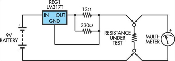
This adaptor circuit is essentially a 100mA constant current source. It is applied across a low-value resistor of unknown value (ie, the resistance to be measured) and the resulting voltage drop can then be measured by a digital multimeter (DMM). Setting your DMM to the 200mV range will enable it to measure up to 2O with high resolution while the 2V range will give a maximum resistance measurement of 20O. Construction could consist of mounting the LM317 adjustable 3-terminal regulator inside a small plastic box together with the battery and two resistors connected to the output and Adj pins.Circuit diagram:
No on/off switch is required since no current will be drawn when no external resistance is connected across the Test terminals. Accuracy using 1% resistors should be within 5% and this could be improved by measuring the current, adjusting the resistance between the output and Adj pins of the LM317 to provide a precise 100mA. Before using the adaptor, check that your meter is not likely to be damaged by having the full output (6V+) applied when it is set to a low voltage range. Similarly, be aware that the voltage and current output of the adaptor may damage components if you use it for "in-circuit" tests.
Author: Peter Chamberlain - Copyright: Silicon Chip

