Home » Circuits
Room Noise Detector Circuit Schematic
One LED monitors three levels: 50, 70 & 85 dB, Useful to detect too noisy environments
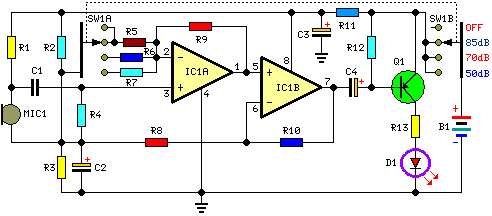
This circuit is intended to signal, through a flashing LED, the exceeding of a fixed threshold in room noise, chosen from three fixed levels, namely 50, 70 & 85 dB. Two Op-amps provide the necessary circuit gain for sounds picked-up by a miniature electret microphone to drive a LED. With SW1 in the first position the circuit is off. Second, third and fourth positions power the circuit and set the input sensitivity threshold to 85, 70 & 50 dB respectively. Current drawing is 1mA with LED off and 12-15mA when the LED is steady on.
Circuit diagram:
Parts:
R1 = 10K
R2 = 22K
R3 = 22K
R4 = 100K
R5 = 56K
R6 = 5.6K
R7 = 560R
R8 = 2.2K
R9 = 56K
R10 = 56K
R11 = 1K
R12 = 33K
R13 = 330R
C1 = 100nF-63V
C2 = 10µF-25V
C3 = 470µF-25V
C4 = 47µF-25V
D1 = 5mm. Red LED
Q1 = BC327
B1 = 9V PP3 Battery
SW1 = 2 poles 4 ways rotary switch
IC1 = LM358 Low Power Dual Op-amp
MIC1 = Miniature electret microphone
Use:
- Place the small box containing the circuit in the room where you intend to measure ambient noise.
- The 50 dB setting is provided to monitor the noise in the bedroom at night. If the LED is steady on, or flashes bright often, then your bedroom is inadequate and too noisy for sleep.
- The 70 dB setting is for living-rooms. If this level is often exceeded during the day, your apartment is rather uncomfortable.
- If noise level is constantly over 85 dB, 8 hours a day, then you are living in a dangerous environment.
| dB | Example of sound sources |
|---|---|
| 20 | Quiet garden, electric-clock ticking, drizzling rain |
| 30 | Blast of wind, whisper @ 1 m. |
| 40 | Countryside areas, quiet apartment, wrinkling paper @ 1 m. |
| 50 | Residential areas, quiet streets, fridges, conversation @ 1 m. |
| 55 | Offices, air-conditioners |
| 60 | Alarm-clocks, radio & TV sets at normal volume |
| 64 | Washing machines, quiet typewriters |
| 67 | Hair-dryers, crowded restaurants |
| 69 | Dish-washers, floor-polishers |
| 70 | Loud conversation, noisy street, radio & TV sets at high volume |
| 72 | Vacuum cleaners |
| 78 | Telephone ring, mechanical workshop |
| 80 | Passing trucks, noisy hall or plant, shuffling @ 1 m. |
| 90 | Passing train, pneumatic hammer, car hooter @ 1 m. |
| 95 | Mega "disco", circular saw |
| 100 | Motorcycle without silencer |

