Home » Circuits
Simple Logic Probe
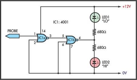
This simple logic probe has both LEDs on with no signal at the input but due to the nor gates connected to the probe, indicates correctly when a high or low signal is present. It also works correctly for pulse trains. Normally both LEDs are forward biased and therefore on, powered by the 12V supply. When a logic "high" is present at the probe, IC1a's output goes low sending IC1b's output high. This turns off LED1 but forward-biases (and turns on) LED2. Conversely, a logic "low" at the probe will send IC1b low, turning LED1 on and LED2 off.Circuit diagram:
Author: F. Edwards

