7.2 volt NiCad Cycler


Table 1
Part Description Radio Shack # DigiKey # Notes
IC1  TL431(ILP) Motorola
 LM431
 NTE999
 n/a  296-1292-ND  Adj. Shunt Reg., TO-92
R1, R4  820 Ohm resistor     820QBK-ND  white red brown gold
R2, R3  5 ohm, 25W, WW      green brown brown gold
P1  10K trimmer     3292W-103-ND  10-turn
D1  LED, red  276-033    high brightness
D2  1N4001 diode  276-1101  1N4001DICT-ND  50V, 1A, rectifier
K1  5 volt relay  275-240    1-amp or better
S1  switch, momentary 'on'  275-1547    sub miniature

A KIT for this project is available here: [7.2V NiCad Cycler]

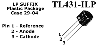
Technical Notes: This NiCad cycler is based on the Motorola Solid-State precision voltage reference device, TL431(ILP). The trip point can be set to 6.6 volt or whatever else you prefer for your 7.2 volt battery pack. Radio Shack can order this part in I was told.TL431 pins TL431ILP senses the preset voltage reference and trips the relay when that control voltage point is reached, adjusted with the 10-turn trimmer potentiomer, which in turn activates the charger. The resistors used in this circuit provide an approximate discharge rate of 250mA. Since the remainder of the circuits' power is also provided by the battery being discharged, an additional 50mA or so is discharged from the NiCad battery packs. The relay is configured as a latch so that once the unit trips from discharge to charge, the unit cannot be recycled until the start switch is pressed again. The component values, setting up the discharge value and trip poins can be adjusted to handle any size or battery voltage up to the 30 volt maximum rating of the TL431. Remember, the relay coil voltage must also be taken into consideration when changing the operating voltage of the circuit. All components listed in the circuit can be easily obtained from your local electronics store or Tandy/Radio Shack, although the TL431 may have to be ordered in. If you find a significant drop in discharge time you have a clue that something is going bad with your pack and close examination or a new purchase may be needed.
R2 and R3 are preferable wire-wound resistors

Description and Calibration: When you have completed building the cycler, go back and make sure that all your connections are soldered solidly and that all connections are correct. If you're not sure, try to get help from someone with electronics experience. Although highly unlikely, it is possible to destroy the TL431 by reversing the positive/negative connections so try to make sure this particular device is hooked up correctly. Take your time checking your wiring and connections; the last thing you want is damage to your charger.
To calibrate this unit you need an adjustable power supply since the 7.2 volts cannot be obtained with the regular 1.5 volt dry cells. You can easily construct the one listed here very cheap, with parts you may already have in your parts box, and keep it for future calibration of the cycler circuit if you ever have to replace a component.
A NiCad battery pack will also not work for this step in the process. You need an adjustable Power Supply and set the voltage to about 7 volts.
Your goal in calibrating the cycler is to adjust the trimmer in such a way that the unit will change from 'discharge' to 'charge' when the cells reach 1.1 volts per cell, which will mount to 6.6 volts total.
Preset the trimmer control all the way to one end. If you followed the the parts list above you will have about 10-turns to go from one end to the other, and believe me, with a regular trimpot adjusting the cycler is almost impossible. A 10-turn trimmer is a necessity!
The power supply, at 7 volt, is just above the voltage you want the receiver pack to change over from 'cycle' to 'charge'.
Connect the power supply across the receiver battery leads of the cycler. Press and release the start button. If the LED lights and stays lit, turn the control all the way to the other end, and repeat the step above. Now turn the trimmer otentiometer back 1/8 turn, in the opposite direction you turned it to get the LED to go off. Press and release the start button one more time. IF the LED stays on, the receiver battery adjustment portion of the cycler is complete. If the LED still goes out, turn the trimmer an additional 1/8 turn back. Now the LED shoud stay lit when the start button is pressed and released. If it does not, or the relay seems to 'rattle' when you press the start button recheck your wiring; something is not connected right.
What exactly should that trigger-level be, you may ask? It should be the set-point where you wish to start the charge-cycle. At 1.1volt/cell that would be 6.6 volt. You may like it a bit higher like 6.8volt (1.13 volt/cell). So what you do is you keep adjusting the trimpot until it starts the 'charge' cycle at 6.8volts. Easy huh? Mine is set for 0.9 volt/cell which is not recommended for all nicad batteries and is definately not for the faint of heart. My packs are over 8 years old and still going strong. I cycle all my nicads once a month, no matter if I use(d) them or not.

CAUTION: Do NOT plug your wall charger in during the calibration procedure. It should only be plugged in when the NiCad is connected to the cycler!
Once you completed the adjustments, connect your fully charged NiCad pack to the cycler. Plug in the wall charger. The LED on your wall charger should be on indicating the pack are being charged. If not, check your wiring again. Now press and release the start button. The Led on the cycler should go on and the led on the wall charger go out. This state indicates your battery pack being 'discharged'. When the led on the wall charger is on, the battery is being charged. About 16-hours after the cycler has switched from discharge to charge, your battery pack is ready for use.
Remember, you must allow the battery pack to fully charge before flying. I don't need to remind you to check the battery voltage with your expanded scale voltmeter before each flight.
Also note that the adjustment can be bit tricky, so just take your time and be patient.

Most 7.2 volt NiCads should not be "slow-charged". They should always be fast-charged (if so noted on the pack) to maintain their power/current drain for fast and optimum performance. See some primers on NiCads. I use a 9-volt -1200mA adapter from an old answering machine. Use anything you have laying around but not to exceed 9 or 10Volt-DC and not less than 500mA.
The TL431 looks like an ordinairy transistor but it is not; the TL431 is a "precision voltage reference" IC (Integrated Circuit).

The phone number for DigiKey is 1-800-Digi-Key.

Back to Gadgets Menu page
Copyright ©1996 - Tony van Roon