Home » Circuits
3 Volts Car Adapter Using LT1074CT
This circuit is based on a standard LT1074CT switching regulator IC. For sure, Application Note AN35 published by Linear Technology describes the design far more elegantly than the author could in this short article. Interested readers are therefore strongly advised to get a copy of AN35. The schematic shows the LT1074CT used as a positive step-down or ‘buck’ converter. The ‘switcher’ is used to convert a +12-volt car battery voltage down to +3 volts for use with the personal hi-fi’s and hand-held games for the author’s two boisterous children on long car journeys. Note at under ten years of age, children will rarely be hi-fi aficionado’s and are generally not concerned with any noise generated by the ‘switcher ‘circuit.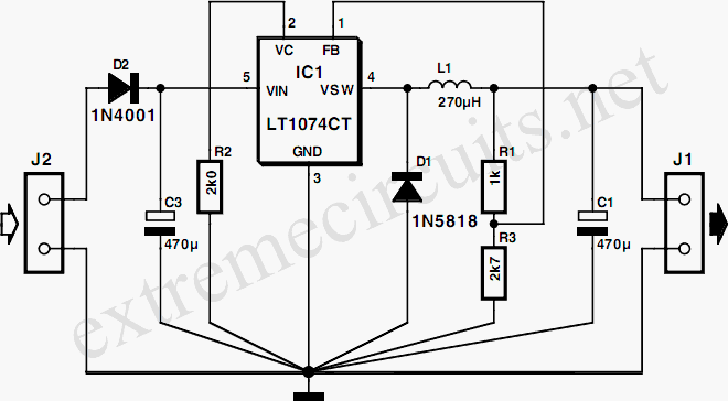 The circuit is connected to the car +12-V system via the cigarette lighter socket — is advisable to use a fused version of the cigarette lighter plug. The +12-V arrives on the board via screw- terminal block J2. Diode D2 provides a reverse voltage protection, while C3 decouples the input to the switcher IC. The LT1074CT briskly switches the supply voltage on and off in response to the signal applied to its F/B input, to the extent that the average output voltage is at the required level. The values of potential divider resistors R1-R3 have been chosen to attenuate the output voltage so that there is 2.5 V at the F/B pin.
The difference between the attenuated output voltage and the internal 2.5-V reference is used to control the modulation effect of the switcher. Components R2 and C2 provide frequency stabilization for the feedback loop. Inductor L1 along with the LT1074CT form the main switching components, while C1 provides decoupling for the output load. The 3-V output voltage is taken from screw terminal J1. With this circuit built, boxed up and installed in your car, you can look forward to possibly your first ‘quiet’ long car journey.