Home » Circuits
Audio Booster
Small and portable unit, Can be built on a veroboardThe amplifier's gain is nominally 20 dB. Its frequency response is determined primarily by the value of just a few components-primarily C1 and R1. The values of the schematic diagram provide a response of ±3.0 dB from about 120 Hz to better than 20,000 Hz.Actually, the frequency response is ruler flat from about 170 Hz to well over 20,000 Hz; it's the low end that deviates from a flat frequency response. The low end's roll-off is primarily a function of capacitor C1(since RI's resistive value is fixed). If C1's value is changed to 0.1 pF, the low end's comer frequency-the frequency at which the low-end roll-off starts-is reduced to about 70 Hz. If you need an even deeper low-end roll-off, change C1 to a 1.0 pF capacitor; if it's an electrolytic type, make certain that it's installed into the circuit with the correct polarity, with the positive terminal connected to Q1's base terminal.
Circuit diagram:
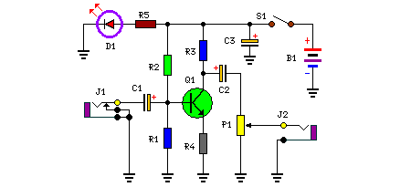
Parts:
P1 = 100K
R1 = 47K
R2 = 470K
R3 = 10K
R4 = 560R
R5 = 270R
C1 = 0.1uF-25v
C2 = 3.3uF-25v
C3 = 470uF-25V
D1 = 5mm. Red Led
B1 = 9v Battery
J1 = RCA Audio Input Socket
J2 = RCA Audio Output Socket
S1 = On-Off Switch