Home » Circuits
Automatic Light Dimmer
In many cases, the dimmer presented here may be built into a wall-mounted box containing the light switch. It is intended for use with 240 V incandescent lamps only. When it is fitted, and the light is switched on, the lamp does not come on fully for about 400 ms (which is not noticeable). When the light is switched off, it stays on unchanged for about 20 s, and then goes out gradually. This has the advantage that it is not immediately dark when the light is switched off. When light switch S1 is turned on, capacitor C2 is charged via R1, C1 and bridge rectifier D1–D4. Zener diode D5 limits the potential across C2 to about 15 V. After a short while, diode D6 lights, whereupon a potential difference ensues across light sensitive resistor R3, which is sufficient to trigger triac Tr1.Circuit diagram:
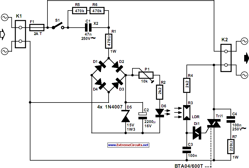
The light then comes on. When the light switch is turned off, C2 is discharged via P1, R2 and D6. When the potential across C2 drops, the brightness of the LED diminishes, so that the p.d. across R3 also drops. The increasing resistance of R3 effects phase angle control of the triac so that the light is dimmed gradually. The dimming time may be altered with P1 within the time range determined by network R2-C2. The circuit operates correctly only, of course, when the LDR is not exposed to light other than that from the LED. The type of LDR is not particularly important, as long as it is not too long: in the prototype, a model with a length of 5 mm was used.
Author:Schallmoser
Copyright: Elektor Electronics
Copyright: Elektor Electronics