Home » Circuits
Battery-Charging Indicator For Mains Adaptor
Although you may well be the proud owner of the very latest NiCd battery charger, you may still come across the odd 'incompatible' battery, for example, one having a rare voltage or requiring a much higher charging current than can be supplied by your off-the-shelf charger. In these cases, many of you will resort to an adjustable mains adaptor (say, a 500-mA type) because that is probably the cheapest way of providing the direct voltage required to charge the battery. Not fast and not very efficient, this 'rustic' charging system works, although subject to the following restrictions:Circuit diagram:
- You should have some idea of the charging current. In case you use an adaptor which is adjustable but of the unregulated, low output current type, you can adjust the current by adjusting the output voltage.
- You have to know if the current actually flows through the battery. A current-detecting indicator is therefore much to be preferred over a voltage indicator.
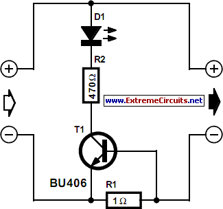
- To prevent you from forgetting all about the charging cycle, the indicator should be visible from wherever you pass by frequently. Using the circuit shown here, the LED lights when the baseemitter potential of the transistor exceeds about 0.2 V. Using a resistor of 1 ? as suggested this happens at a current of about 200 mA, or about 40 mA if R1 is changed to 4.7?. The voltage drop caused by this indicator can never exceed the base-emitter voltage (UBE) of the transistor, or about 0.7V. Even if the current through R1 continues to increase beyond the level at which UBE = 0.7 V, the base of the transistor will 'absorb' the excess current. The TO-220 style BU406 transistor suggested here is capable of accepting base currents up to 4A. Using this charging indicator you have overcome the restrictions 2 and 3 mentioned above.