Home » Circuits
Body Charge Detector
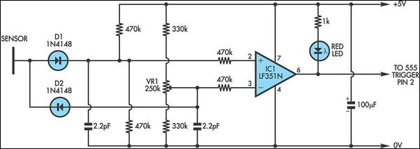
It is well known that through such simple everyday activities as walking on a carpet or moving in a chair, the body accumulates a static charge - sometimes many thousands of volts. Due to its extreme sensitivity, this circuit will detect not only such charges but also EMF-induced voltages in the body, which are generally far smaller. This means that, whether you happen to be "charged up" on any particular day or not, your body will almost certainly trigger this circuit.An interesting twist is that the sensor does not need to be made of metal. Provided it is isolated from ground, the sensor can be any conductor, including a plant in a pot. The circuit is a comparator based on an LF351 FET-input op amp (IC1). The has the benefit of a high impedance input which is crucial for detecting a static charge. The other aspect which is crucial is that the 0V side of the circuit must be connected to earth (eg, a metal stake driven into the ground). Without the grounded connection, the circuit will yield poor results.
Circuit diagram:
Notice that the sensor connections are taken through diodes D1 and D2. This means that both negative and positive charges will cause the voltage at IC1's inverting input to exceed that of the non-inverting input (the voltage at the inverting input rises or that at the non-inverting input falls). Trimpot VR1 and the two 470kO resistors across the supply are used to set the inverting and non-inverting inputs (pins 2 and 3) at around half-supply (ie, +2.5V), while the two 470kO input resistors protect IC1 against damage from static.
The sensitivity of the circuit is adjusted by VR1. While higher static charges will brightly flash the red LED, small and very rapid discharges through the sensor may barely illuminate it. The way around this is to feed the output at pin 6 directly to the trigger input (pin 2) of a standard 555 monostable timer IC. This would then offer a clearer indication of triggering. This circuit could prove particularly useful as an indicator of static charge before handling sensitive components.
Author: Thomas Scarborough - Copyright: Silicon Chip Electronics

