Home » Circuits
Cable Analyser
Many constructors have various cables lying around and after a time do not know any longer what they are for or what their pin connections are. It is not always possible to check this with a multimeter. The analyser may be of help in such a situation. In most cases, an analyser for checking cables with D9 and D25 connectors will suffice. The shape of the analyser will depend to a large extent on the type of cable to be checked. It may be made as a connector, as a bus, or as a feed-through cable. Since only standard components are needed, the cost is low.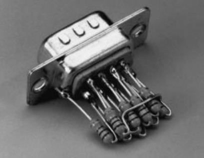 Solder a resistor of 1 kΩ between pin 1 of the analyser and the case; one of 2 kΩ between pin 2 and the case, and so on, increasing the value of the resistor by 1 kΩ for each successive pin. When this is completed, connect the analyser to the cable to be tested and measure the resistance between pin 1 and the case. The value so obtained in kilohms is the number of the pin at the other end of the cable. The arrangement is shown in the diagram. If at all possible, use resistors in the E96 series, since these give best accuracy.
Since this design was completed, a reader has suggested a simple improvement to it, whereby the nine resistors are linked in series instead of in parallel. The great advantage of this simplification is that all nine resistors have the same value: 1 Ω or 1 kΩ. The test method remains the same: the value in Ω or kΩ measured on the multimeter is the nuber of the pin at the other end of the cable.