Home » Circuits
Floating 9V Supply For DVM Modules
Most commercial DVM modules with an LCD readout are 9-V powered and based on an ICL7106 or similar A-D converter chip. These modules are typically used in laboratory power supplies and other test and measurement equipment where a drop-in solution needs to be found to realize a voltmeter readout. Particularly in power supply units, the LCD module will need to ‘float’ relative to the PSU supply rails, and this inevitably requires a separate 9-volt power supply. In some cases, batteries may be used but these have distinct advantages. The alternative, a 9-V converter effectively powered by the PSU and yet floating, is shown here.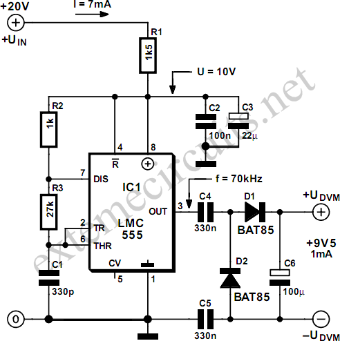
It is built from the ubiquitous TLC555, LMC555 or 7555) timer IC acting in astable multivibrator configuration producing a 70-kHz square wave fed into a simple rectifier. In essence, capacitors C5 and C6 afford the above mentioned electrical isolation between the PSU supply rails and the LCD module. The old, bipolar NE555 IC should not be used here because it presents a too heavy loads on the converter’s own supply voltage. Depending on the exact type and brand of the CMOS 555 you’re using, resistor R6 may need to be redimensioned a bit to ensure a supply voltage of about 10 volts at pins 8 and 4 of the chip. At an output voltage of 9.5 V, the maximum output current of the converter s about 1 mA.