Home » Circuits
High Power Headphone Amplifier Using BD139-40
Firstly, I'd like to stress that the intended use of this circuit is only one of many possible applications. Apart from the obvious usage as a headphone amplifier, the circuit can be used for a range of applications where a wide bandwidth low power amplifier is needed. Some of the options include ...- Reverb drive amplifier - ideal for low and medium impedance reverb tanks
- High current line driver - suitable for very long balanced lines
- Low power speaker amplifier - better performance than small integrated amps
- ... and of course, a headphone amp.
As a headphone amplifier, this design is very similar to others on the ESP site, but the main difference is that this one (and P70) has been built and fully tested. The design is fairly standard, and every variation was checked out before arriving at the final circuit. A photo of the prototype is shown below, and at only 64 x 38mm (2.5 x 1.5 inches) it is very small - naturally, the heatsink is not included in the dimensions.
The amplifier is capable of delivering around 1.5W into 8 ohm headphones, and 2.2W into 32 ohms - this is vastly more than will ever be needed in practice. The use of a 120 Ohm output resistor is recommended, as this is supposed to be the standard source impedance for headphones. Unfortunately, many users have found that their 'phones perform better when driven from a low impedance source.
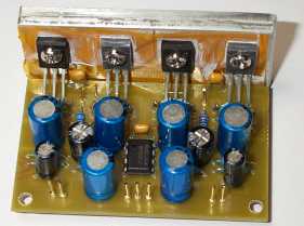 Prototype Headphone Amplifier
The circuit is based on an opamp, with its output current boosted by a pair of transistors. Distortion is well below my measurement threshold at all levels below clipping into any impedance. Noise is virtually non-existent - even with a compression driver held to my ear, I could barely hear any, and I couldn't hear any with headphones.
WARNING
Headphones are rated in dB SPL at 1mW, and this amplifier (like many other similar headphone amps) is capable of producing extreme SPLs. The levels obtainable are sufficient to cause almost instantaneous permanent hearing damage! Never operate the amp at very high levels, and never switch the amplifier on with signal while wearing you headphones.
Always start with the volume control at minimum, and gradually increase the level until it is comfortable, but not too loud. Because of the very low distortion, it is easy to increase the level too far without noticing. Your ears are precious - safeguard them at all times.
Note the warning above - this is serious. Most headphones are capable of at least 94dB SPL at 1 mW, with some as high as 107dB SPL. Even 10mW is enough to create sound levels capable of causing hearing damage, so you must be very careful to avoid damaging levels.
| Continuous dB SPL | Maximum Exposure Time |
| 85 | 8 hours |
| 88 | 4 hours |
| 91 | 2 hours |
| 94 | 1 hour |
| 97 | 30 minutes |
| 100 | 15 minutes |
| 103 | 7.5 minutes |
| 106 | < 4 minutes |
| 109 | < 2minutes |
| 112 | ~ 1 minute |
| 115 | ~ 30 seconds |
Note that the exposure time is for any 24 hour period, and is halved for each 3dB SPL above 85dB. The above shows the accepted standards for recommended permissible exposure time for continuous time weighted average noise, according to NIOSH (National Institute for Occupational Safety and Health) and CDC (Centers for Disease Control). Although these standards are US based, they apply pretty much equally in most countries - hearing loss does not respect national boundaries.
Description
The amplifier itself is fairly conventional, and is very similar to another shown on this site (see Project 24). This amplifier does not include the active volume control, because in general it is far easier to get a good log pot (or simply 'fake' the pot's law as described in Project 01). Likewise, it does not include the cross-feed described in Project 109. If this is desired, it is very easy to implement on a small piece of tag board, or even 'sky hook' the few components off the bypass switch. Full details of how to do this will be included in the construction guide when PCBs are available.
The output transistors are biased using only resistors, rather than constant current sources. Extensive testing showed that using current sources made no discernible difference to performance, but increased the complexity and PCB size. Using separate caps for each biasing diode does make a difference though - and although it is relatively minor, the use of the two caps is justified IMHO.
The bias diodes should be 1N4148 or similar - power diodes are not recommended, as their forward voltage is too low. This may result in distortion around the crossover region, where one transistor turns off and the other on. As shown, crossover distortion is absolutely unmeasurable with the equipment I have available.
 Figure 1 - Headphone Amplifier Circuit Diagram
Above is the schematic of one channel. Resistors and caps use the suffix 'R' for the right channel. The second half of the dual opamp powers the right channel. Note that the volume control shown is optional, and is not on the PCB. If needed, it may be mounted in a convenient location and the output connected to the inputs of the board as shown. D1 and D2 (L and R) are 1N4148 or similar.
One of the reasons the amp is so quiet is that the entire board runs from a regulated supply, so hum (in particular) is eliminated. Although an unregulated supply can be used, this is not recommended. The supply should be separate from that used for your preamp, because of the relatively high current drawn by the amplifier (at least with low impedance 'phones). A P05 preamp supply can be used, and will ensure optimum performance.
The prototype amplifier has flat frequency response from 10Hz to over 100kHz. Distortion is below my measurement threshold with any level or load impedance, and output impedance is almost immeasurably low. Your headphones may be designed to operate from a 120Ω source impedance (many are), so this may be added if it improves sound quality. Adding any series resistance will reduce the available power, but it is already far greater than you can use. Without series resistance, the minimum power into various load impedances is given below (based on ±15V supplies).
| Impedance | Power (Direct) | 120 Ohm Feed |
| 8 Ohms | 1.5 W | 35 mW |
| 32 Ohms | 2.2 W | 99 mW |
| 65 Ohms | 1.1 W | 136 mW |
| 120 Ohms | 595 mW | 149 mW |
| 300 Ohms | 238 mW | 121 mW |
| 600 Ohms | 119 mW | 82 mW |
Construction
While it may be possible to build it using Veroboard or similar, there is a high risk that it will oscillate because of the very wide bandwidth of the amplifier. A capacitor may be added in parallel with R4 (L and R) to reduce the bandwidth if stability problems are encountered. Although I used an NE5532 opamp for the prototype, the circuit will also work with a TL072, but at reduced power. You may also substitute an OPA2134 or your favorite device, taking note of the following ...
 The standard pinout for a dual opamp is shown on the left. If the opamps are installed backwards, they will almost certainly fail, so be careful.
The suggested NE5532 opamp was used for the prototype, and performance is exemplary. Devices such as the TL072 will be quite satisfactory for most work, but if you prefer to use ultra low noise or wide bandwidth devices, that choice is yours.
Construction is fairly critical. Because of the wide bandwidth of the NE5532 and many other audio grade opamps, the amplifier may oscillate (the prototype initially had an oscillation at almost 500kHz), so care is needed to ensure there is adequate separation between inputs and outputs. Even a small capacitive coupling between the two may be enough to cause problems.
As shown in the photo, this amplifier needs a heatsink. While it can operate without one at low power using high impedance headphones, you need to plan for all possibilities (after all, you may purchase low impedance 'phones sometime in the future). The heatsink does not need to be massive, and the one shown above is fine for normal listening levels. An aluminium bracket may be used to attach to the chassis - I recommend 3mm material. Note that the heatsink should always be earthed (grounded).
The output transistors must be insulated from the heatsink. Sil-Pads™ are quite suitable because of the relatively low dissipation, but greased mica or Kapton can be used if you prefer. If you use the suggested 3mm aluminium, you can drill and tap threads into the heatsink, removing the need for nuts.
Testing
Connect to a suitable power supply - remember that the supply earth (ground) must be connected! When powering up for the first time, use 56 ohm "safety" resistors in series with each supply to limit the current in case you have made a mistake in the wiring. These will reduce the supply voltage considerably because of the bias current of the output transistors.
If the voltage at the amplifier supply pins is greater than ±6V and the output voltage is close to zero, then the amplifier is probably working fine. If you have an oscilloscope, check for oscillation at the outputs ... at all volume control settings. Do this without connecting your headphones - if the amp oscillates, it may damage them.
Once you are sure that all is well, you may remove the safety resistors and permanently wire the amplifier into your chassis.
source: http://sound.westhost.com/project113.htm
Contents sponsored by Elektor for 3 months only. Sign up for Elektor Weekly now.