Home » Circuits
How To Connect Two Computers Using Modems
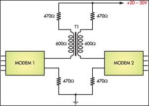
Have you ever connected two PCs together via modems using a twisted pair cable and nothing happened? That’s because the modems are expecting a phone line with all the signals and voltages supplied by the local telephone exchange. This circuit simulates the DC power and signal isolation but not the "dial tone" or the "ring signal". It suffices to connect two PCs together to communicate and exchange files using HyperTerminal. The circuit is self-explanatory and needs only one power supply for both modem lines. Although 50V DC is the usual exchange line voltage, this circuit should operate down to 20V. A 600O line transformer (eg. Jaycar cat. MM-1900) provides signal isolation, while the resistors provide current limiting and keep the lines as balanced as possible.Circuit diagram:
When using this set-up with HyperTerminal, you should not select a Windows modem driver in the "Connect To" dialog. Instead, connect directly to the relevant COM port. Next, verify that the modems are working by sending information commands such as "ATI1" or "ATI3". If you don’t get a response using these commands, try resetting the modem(s) using the "AT&Z" command. Assuming you do get a response, set one in originate mode using the "ATD" command and the other in answer mode with the "ATA" command. If all is well, you should now be able to type in one terminal window and see the results echoed in the second PC’s terminal window. To return to control mode, type "+++". The advantage of using modems instead of a serial cable between COM ports is that the two PCs can be kilometres apart instead of a few metres. For example, you could connect the house PC to the workshop PC on the other side of the farm.
Author: Filippo Quartararo
Copyright: Silicon Chip Electronics
Copyright: Silicon Chip Electronics