Home » Circuits
Irregular Flasher
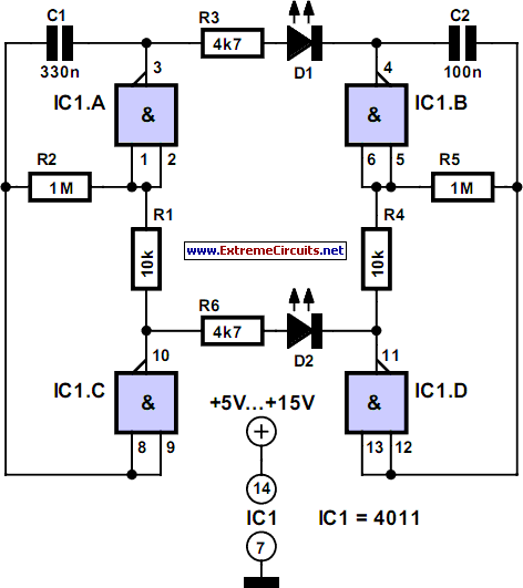
Two multivibrators with different frequencies can be built using the NAND gates of a 4011 IC. If the output of IC1.B is positive with respect to IC1.C, LED D1 is on. As the levels of IC1.A and IC1.D are exactly opposite, D2 is always on when D1 is off, and the other way around. The two oscillators have different frequencies, which are determined by the values of R2/C2 and R5/C5 respectively according to the formula f0 = 1 ÷ (1.4 RC) With the given component values, the frequencies are 2.2 Hz and 7.2 Hz. Low-current LEDs should be used, since the CMOS IC cannot sink or source sufficient current for ‘normal’ LEDs.Circuit diagram:
The values of series resistors R3 and R6 are suitable for a supply voltage of 12 V, in which case the current consumption of the circuit is around 5 mA. However, in principle the 4011 can be operated over a supply voltage range of 5–15 V. Higher currents can be provided by the HC family (supply voltage 3–6 V) or the HCT family (5 V). Incidentally, the part number of the quad gate IC in the HC family is HC7400.
Author: Ludwig Libertin - Copyright: Elektor July-August 2004

