Home » Circuits
Low Battery Indicator II
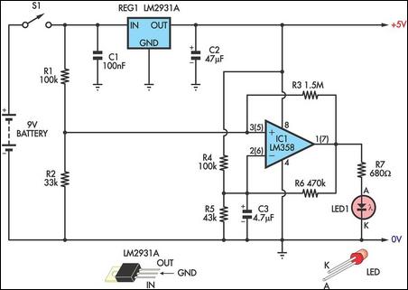
This circuit indicates the remaining battery life bAy varying the duty cycle and flash rate of an LED as the battery voltage decreases. In fact, the circuit actually indicates five battery conditions: (1) a steady glow assures indicates that the battery is healthy; (2) a 2Hz flicker (briefly off) indicates that the battery is starting to show age; (3) a 5Hz 50% duty-cycle flash is a warning that you should have a spare battery on hand; (4) a brief flicker on at a 2Hz rate indicates the battery's last gasp; and (5) when the LED is continuously off, it's time to replace the battery. IC1 is wired as an oscillator/comparator, with a nominal fixed voltage reference of about 1.5V on its pin 2 (inverting) input (actually, it varies between about 1.7V and 1.4V depending on the hysteresis provided via R6).Circuit diagram:
This reference voltage is derived from a voltage divider consisting of resistors R4 & R5, which are connected across the 5V rail derived from regulator REG1, and feedback resistor R6. Similarly, IC1's pin 3 input (non-inverting) is connected to a voltage divider consisting of R1 & R2 which are across the 9V battery. Using the component values shown, the circuit will switch LED1 from being continuously on to flash mode when the 9V battery drops to about 6.5V. Subsequently, LED1 is continuously off for battery voltages below 5.5V.
Naturally, you can tweak the resistor values in the divider network for different voltage thresholds as desired. In operation, the circuit oscillates only when the sampled battery voltage (ie, the voltage on pin 3) is between the upper and lower voltage thresholds set on pin 2. Capacitor C3 provides the timing. Above and below these limits, IC1 simply functions as a comparator and holds LED1 continuously on or off. Finally, to precisely set the "dead-battery" threshold, make R4 adjustable to offset the variations in regulator tolerance.
Author: Ashish Nand - Copyright: fgf

