Home » Circuits
Mini Audio Signal Generator
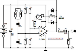
A small audio test generator is very useful for quickly tracing a signal through an audio unit. Its main purpose is speed rather than refinement. A single sine-wave signal of about 1 kHz is normally all that is needed: distortion is not terribly important. It is, however, important that the unit does not draw too high a current. The generator described meets these modest requirements. It uses standard components, produces a signal of 899 Hz at an output level of 1 V r.m.s. and draws a current of only 20 µA. In theory, the low current drain would give a 9 V battery a life of 25,000 hours. The circuit is a traditional Wien bridge oscillator based on a Type TLC271 op amp. The frequency determining bridge is formed by C1, C2 and R1–R4. The two inputs of the op amp are held at half the supply voltage by dividers R3-R4 and R5-R6 respectively.Circuit diagram:

Resistors R5 and R6 also form part of the feedback loop. The amplification is set to about ´3 with P1. Diodes D1 and D2 are peak limiters. Since the limiting is based on the non-linearity of the diodes, there is a certain amount of distortion. At the nominal output voltage of 1 V r.m.s., the distortion is about 10%. This is, however, of no consequence in fast tests. Nevertheless, if 10% is considered too high, it may be improved appreciably by linking pin 8 of IC1 to ground. This increases the current drain of the circuit to 640 µA, but the distortion is down to 0.7%, provided the circuit is adjusted properly. If a distortion meter or similar is not available, simply adjust the output to 1 V r.m.s. Since the distortion of the unit is not measured in hundredths of a per cent, C1 and C2 may be ceramic types without much detriment.
