Home » Circuits
Processor Fan Control
Fans in PCs can be objectionably loud. In many cases, the amount of noise produced by the fan can be considerably reduced by lowering its speed. Although this will decrease the amount of cooling, this need not be a problem as long as you don’t go overboard with slowing down the fan. Particularly with older-model processors, which consume quite a bit less power than the latest models, this trick can be used without any problems. This circuit is anyhow intended to be used with relatively old PCs, since more recent models generally have a fan control circuit already integrated into the motherboard. These controllers ensure that the amount of cooling is increased if the processor becomes too warm and decreased if the processor temperature is relatively low.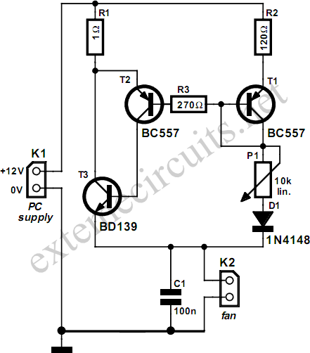 The circuit described here consists of only a handful of components, which you will probably already have in a drawer some-where. Transistors T1 and T2 are driven into conduction by the base current flowing to the fan via P1 and D1. There will always be a current flowing through R1, and it will be approximately 120 times as large as the current through R2. R3 has been added to prevent the base current of T2 from becoming too large when P2 is set to its minimum resistance. D1 ensures that even at this extreme setting, the voltage on the base-emitter junction of T3 will still be large enough to allow it to conduct.