Home » Circuits
Reflector For Pedestrians
Pedestrians run grave dangers when, in badly-lit areas, they cross a road at night in dark clothing, because this means that car drivers may see them too late There are special armbands available that reflect the light of oncoming traffic, telling the driver that there is someone on the road. It is also possible to make an active means of warning car drivers or motorcyclists that you’re crossing the road. It consists of a flat enclosure that houses two PP3 (6AM6; MN1604; 6LR61) 9 V batteries, and the small circuit shown in the diagram. Glue a piece of self-adhesive, reflecting tape (available in the motor trade) on the lid of the enclosure and drill a 10 mm hole in the centre of it.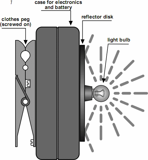 Fit a 6 V bulb in a suitable holder in the 10 mm hole. Fit a suitable clip and, optionally an on/off switch, at the rear of the enclosure. See Figure 1. The electronic circuit consists of a light-sensitive switch, composed of P1, a photoconductive cell, LDR, and IC1a; an inverter, IC1b;, an oscillator, IC1c with R1 and C1; a buffer, IC1d with R2 and T1; and a 6–9 V bulb that draws a current of not more than 50 mA. The photoconductive cell (or light-sensitive resistor) should be exposed to ambient light, but not to the light bulb, of course. Its sensitivity is set with P1.
Circuit diagram:

When the ambient light causes a potential drop across the LDR that is below the level set with P1, IC1a changes state, so that its output goes low, whereupon the output of IC1b goes high, which actuates the oscillator. The buffer then switches the light bulb on and off in the rhythm of the oscillator. Optionally, the light bulb may be replaced by a light-emitting diode rated at 1 cd or higher, and bias resistor. Make sure, however, that the current through the transistor does not exceed its rating of 50 mA. The two 9 V batteries should be connected in parallel. The circuit needs a supply of 3–12 V.