Home » Circuits
Thyristor Tester
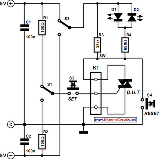
The circuit in the diagram is a very handy tool for rapidly checking all kinds of thyristor (SCR, triac, …). In case of a triac, all four quadrants are tested, which is done with S3, while in case of a standard thyristor, a positive power supply and trigger current need to be set, which is done with S1. The value of resistors R1 and R2 is chosen to obtain a current of about 28 mA, which is more than sufficient for most thyristors. The hold current is determined by R3, and is 125 mA, which is more than adequate to keep the thyristor in conduction after it has been triggered. Since D1 is a red, low-current LED, and D2 a green, low-current LED, it can be seen in a wink in which quadrant the thyristor conducts.Circuit diagram:

Testing is started with S2, and the circuit is reset with S4 after the test has been concluded. Three short lengths of circuit wire terminated into insulated crocodile clips on connector K1 will be found very convenient for linking any kind of thyristor to the circuit. Mind correct connections, though: in the case of a triac, MT1/A1 is linked to earth, the gate to S2 and MT2/A2 to R3; in the case of a standard thyristor, the anode is linked to R3, the cathode to earth, and the gate to S2. If, in a rare case the trigger current needs to be altered, this can be done by changing the value of resistors R1–R3 as appropriate. The trigger current may also be made variable by the use of a variable power supply. If that is done, make sure that the dissipation in the resistors is not exceeded.
