Home » Circuits
Transistor Tester
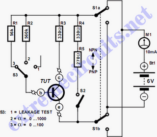
This tester is intended to quickly check whether a transistor is functional or not and possibly also select two or more transistors with (approximately) equal gains. This is about the simplest conceivable test circuit, so don’t expect super accuracy. The circuit has been designed only to quickly carry out a brief check, when there is no time or equipment to carry out a thorough test. The operation is simple: in the position ‘battery test’ (S2 closed), the 10mA moving coil meter M1 in series with a 600 Ω resistor (R4 + R5) is connected to a 6 V battery. A current of 10mA will flow, resulting in full-scale deflection of the meter. When a transistor is being tested (S2 open, S3 in position 2 or 3) a current will flow through the base-emitter junction of the transistor under test, the value of which can be computed by dividing the voltage across R1 or R2 by its resistance. With S3 in position 2 this will be (6 V – 0.6 V)/560 kΩ = approx. 10µA. If the transistor has a gain of 1000 it will cause a collector current (and therefore a meter current) of 10mA, causing full-scale deflection of the moving coil instrument. Therefore, the value indicated by the meter, when S3 is in position 2, has to be multiplied by a factor of 100 to obtain the gain of the transistor. In position 3 the base resistor is 10 times lower (R1 = 56 kΩ), so in this case the reading has to be multiplied by 10 to obtain the gain. It will be clear that position 2 of S3 is intended for high gains of up to 1000 and position 3 for gains of 0 to 100. The purpose of S1 is to reverse the polarity: the upper position drawn is for NPN transistors, the bottom for PNP types. If you have no moving coil instrument available, it is of course also possible to replace M1 with a digital meter.
