Home » Circuits
Very Low Power 32kHz Oscillator
The 32-kHz low-power clock oscillator offers numerous advantages over conventional oscillator circuits based on a CMOS inverter. Such inverter circuits present problems, for example, supply currents fluctuate widely over a 3V to 6V supply range, while current consumption below 250 µA is difficult to attain. Also, operation can be unreliable with wide variations in the supply voltage and the inverter’s input characteristics are subject to wide tolerances and differences among manufacturers. The circuit shown here solves the above problems. Drawing just 13 µA from a 3V supply, it consists of a one-transistor amplifier/oscillator (T1) and a low-power comparator/reference device (IC1).Circuit diagram:
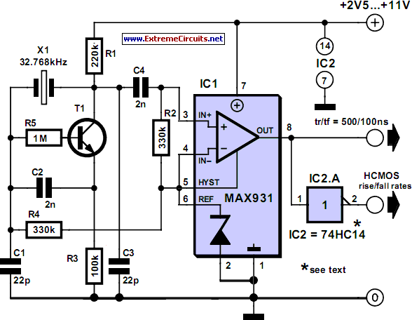
The base of T1 is biased at 1.25 V using R5/R4 and the reference in IC1. T1 may be any small-signal transistor with a decent beta of 100 or so at 5 µA (defined here by R3, fixing the collector voltage at about 1 V below Vcc). The amplifier’s nominal gain is approximately 2 V/V. The quartz crystal combined with load capacitors C1 and C3 forms a feedback path around T1, whose 180 degrees of phase shift causes the oscillation. The bias voltage of 1.25 V for the comparator inside the MAX931 is defined by the reference via R2. The comparator’s input swing is thus accurately centred around the reference voltage.
Operating at 3 V and 32 kHz, IC1 draws just 7 µA. The comparator output can source and sink 40 mA and 5 mA respectively, which is ample for most low-power loads. However, the moderate rise/fall times of 500 ns and 100 ns respectively can cause standard, high-speed CMOS logic to draw higher than usual switching currents. The optional 74HC14 Schmitt trigger shown at the circuit output can handle the comparator’s rise/fall times with only a small penalty in supply current.
Author: D. Prabakaran - Copyright: 2004 Elektor