Mutual inductance
If two coils of wire are brought into close proximity with each other so the magnetic field from one links with the other, a voltage will be generated in the second coil as a result. This is called mutual inductance: when voltage impressed upon one coil induces a voltage in another.
A device specifically designed to produce the effect of mutual inductance between two or more coils is called a transformer.
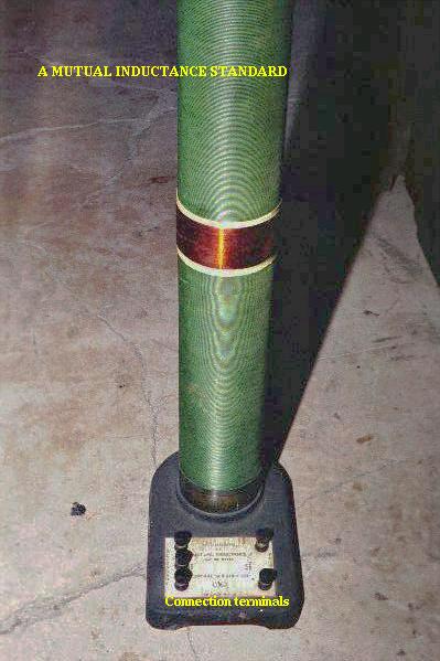
The device shown in the above photograph is a kind of transformer, with two concentric wire coils. It is actually intended as a precision standard unit for mutual inductance, but for the purposes of illustrating what the essence of a transformer is, it will suffice. The two wire coils can be distinguished from each other by color: the bulk of the tube's length is wrapped in green-insulated wire (the first coil) while the second coil (wire with bronze-colored insulation) stands in the middle of the tube's length. The wire ends run down to connection terminals at the bottom of the unit. Most transformer units are not built with their wire coils exposed like this.
Because magnetically-induced voltage only happens when the magnetic field flux is changing in strength relative to the wire, mutual inductance between two coils can only happen with alternating (changing -- AC) voltage, and not with direct (steady -- DC) voltage. The only applications for mutual inductance in a DC system is where some means is available to switch power on and off to the coil (thus creating a pulsing DC voltage), the induced voltage peaking at every pulse.
A very useful property of transformers is the ability to transform voltage and current levels according to a simple ratio, determined by the ratio of input and output coil turns. If the energized coil of a transformer is energized by an AC voltage, the amount of AC voltage induced in the unpowered coil will be equal to the input voltage multiplied by the ratio of output to input wire turns in the coils. Conversely, the current through the windings of the output coil compared to the input coil will follow the opposite ratio: if the voltage is increased from input coil to output coil, the current will be decreased by the same proportion. This action of the transformer is analogous to that of mechanical gear, belt sheave, or chain sprocket ratios:
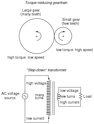
A transformer designed to output more voltage than it takes in across the input coil is called a "step-up" transformer, while one designed to do the opposite is called a "step-down," in reference to the transformation of voltage that takes place. The current through each respective coil, of course, follows the exact opposite proportion.
- REVIEW:
- Mutual inductance is where the magnetic field generated by a coil of wire induces voltage in an adjacent coil of wire.
- A transformer is a device constructed of two or more coils in close proximity to each other, with the express purpose of creating a condition of mutual inductance between the coils.
- Transformers only work with changing voltages, not steady voltages. Thus, they may be classified as an AC device and not a DC device.