Current mirrors
An interesting and often-used circuit applying the bipolar junction transistor is the so-called current mirror, which serves as a simple current regulator, supplying nearly constant current to a load over a wide range of load resistances.
We know that in a transistor operating in its active mode, collector current is equal to base current multiplied by the ratio β. We also know that the ratio between collector current and emitter current is called α. Because collector current is equal to base current multiplied by β, and emitter current is the sum of the base and collector currents, α should be mathematically derivable from β. If you do the algebra, you'll find that α = β/(β+1) for any transistor.
We've seen already how maintaining a constant base current through an active transistor results in the regulation of collector current, according to the β ratio. Well, the α ratio works similarly: if emitter current is held constant, collector current will remain at a stable, regulated value so long as the transistor has enough collector-to-emitter voltage drop to maintain it in its active mode. Therefore, if we have a way of holding emitter current constant through a transistor, the transistor will work to regulate collector current at a constant value.
Remember that the base-emitter junction of a BJT is nothing more than a PN junction, just like a diode, and that the "diode equation" specifies how much current will go through a PN junction given forward voltage drop and junction temperature:
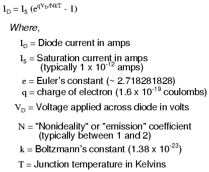
If both junction voltage and temperature are held constant, then the PN junction current will likewise be constant. Following this rationale, if we were to hold the base-emitter voltage of a transistor constant, then its emitter current should likewise be constant, given a constant temperature:
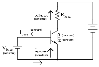
This constant emitter current, multiplied by a constant α ratio, gives a constant collector current through Rload, provided that there is enough battery voltage to keep the transistor in its active mode for any change in Rload's resistance.
Maintaining a constant voltage across the transistor's base-emitter junction is easy: use a forward-biased diode to establish a constant voltage of approximately 0.7 volts, and connect it in parallel with the base-emitter junction:
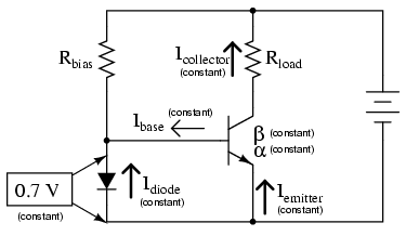
Now, here's where it gets interesting. The voltage dropped across the diode probably won't be 0.7 volts exactly. The exact amount of forward voltage dropped across it depends on the current through the diode, and the diode's temperature, all in accordance with the diode equation. If diode current is increased (say, by reducing the resistance of Rbias), its voltage drop will increase slightly, increasing the voltage drop across the transistor's base-emitter junction, which will increase the emitter current by the same proportion, assuming the diode's PN junction and the transistor's base-emitter junction are well-matched to each other. In other words, transistor emitter current will closely equal diode current at any given time. If you change the diode current by changing the resistance value of Rbias, then the transistor's emitter current will follow suit, because the emitter current is described by the same equation as the diode's, and both PN junctions experience the same voltage drop.
Remember, the transistor's collector current is almost equal to its emitter current, as the α ratio of a typical transistor is almost unity (1). If we have control over the transistor's emitter current by setting diode current with a simple resistor adjustment, then we likewise have control over the transistor's collector current. In other words, collector current mimics, or mirrors, diode current.
Current through resistor Rload is therefore a function of current set by the bias resistor, the two being nearly equal. This is the function of the current mirror circuit: to regulate current through the load resistor by conveniently adjusting the value of Rbias. It is very easy to create a set amount of diode current, as current through the diode is described by a simple equation: power supply voltage minus diode voltage (almost a constant value), divided by the resistance of Rbias.
To better match the characteristics of the two PN junctions (the diode junction and the transistor base-emitter junction), a transistor may be used in place of a regular diode, like this:
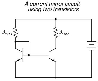
Because temperature is a factor in the "diode equation," and we want the two PN junctions to behave identically under all operating conditions, we should maintain the two transistors at exactly the same temperature. This is easily done using discrete components by gluing the two transistor cases back-to-back. If the transistors are manufactured together on a single chip of silicon (as a so-called integrated circuit, or IC), the designers should locate the two transistors very close to one another to facilitate heat transfer between them.
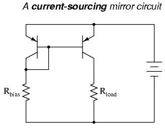
The current mirror circuit shown with two NPN transistors is sometimes called a current-sinking type, because the regulating transistor conducts current to the load from ground ("sinking" current), rather than from the positive side of the battery ("sourcing" current). If we wish to have a grounded load, and a current sourcing mirror circuit, we could use PNP transistors like this:
- REVIEW:
- A current mirror is a transistor circuit that regulates current through a load resistance, the regulation point being set by a simple resistor adjustment.
- Transistors in a current mirror circuit must be maintained at the same temperature for precise operation. When using discrete transistors, you may glue their cases together to help accomplish this.
- Current mirror circuits may be found in two basic varieties: the current sinking configuration, where the regulating transistor connects the load to ground; and the current sourcing configuration, where the regulating transistor connects the load to the positive terminal of the DC power supply.