Noninverting amplifier
PARTS AND MATERIALS
- Operational amplifier, model 1458 or 353 recommended (Radio Shack catalog # 276-038 and 900-6298, respectively)
- Three 6 volt batteries
- Two 10 kΩ potentiometers, linear taper (Radio Shack catalog # 271-1715)
CROSS-REFERENCES
Lessons In Electric Circuits, Volume 3, chapter 8: "Operational Amplifiers"
LEARNING OBJECTIVES
- How to use an op-amp as a single-ended amplifier
- Using divided, negative feedback
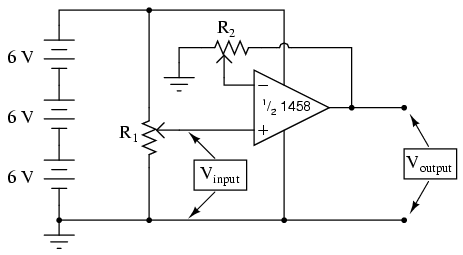
SCHEMATIC DIAGRAM
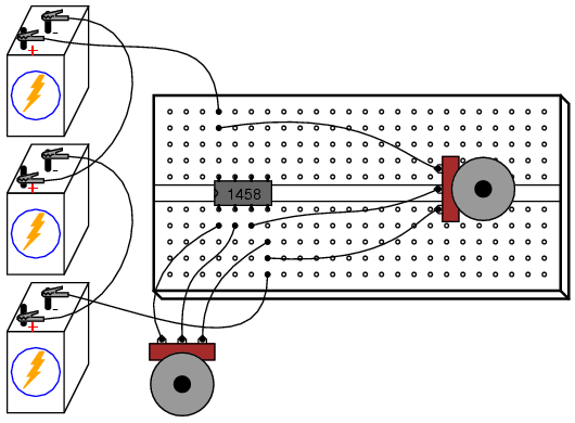
ILLUSTRATION
INSTRUCTIONS
This circuit differs from the voltage follower in only one respect: output voltage is "fed back" to the inverting (-) input through a voltage-dividing potentiometer rather than being directly connected. With only a fraction of the output voltage fed back to the inverting input, the op-amp will output a corresponding multiple of the voltage sensed at the noninverting (+) input in keeping the input differential voltage near zero. In other words, the op-amp will now function as an amplifier with a controllable voltage gain, that gain being established by the position of the feedback potentiometer (R2).
Set R2 to approximately mid-position. This should give a voltage gain of about 2. Measure both input and output voltage for several positions of the input potentiometer R1. Move R2 to a different position and re-take voltage measurements for several positions of R1. For any given R2 position, the ratio between output and input voltage should be the same.
You will also notice that the input and output voltages are always positive with respect to ground. Because the output voltage increases in a positive direction for a positive increase of the input voltage, this amplifier is referred to as noninverting. If the output and input voltages were related to one another in an inverse fashion (i.e. positive increasing input voltage results in positive decreasing or negative increasing output), then the amplifier would be known as an inverting type.
The ability to leverage an op-amp in this fashion to create an amplifier with controllable voltage gain makes this circuit an extremely useful one. It would take quite a bit more design and troubleshooting effort to produce a similar circuit using discrete transistors.
Try adjusting R2 for maximum and minimum voltage gain. What is the lowest voltage gain attainable with this amplifier configuration? Why do you think this is?
COMPUTER SIMULATION
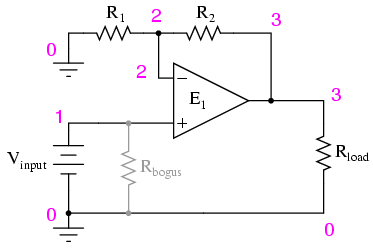
Schematic with SPICE node numbers:
Netlist (make a text file containing the following text, verbatim):
Noninverting amplifier
vinput 1 0
r2 3 2 5k
r1 2 0 5k
rbogus 1 0 1meg
e1 3 0 1 2 999meg
rload 3 0 10k
.dc vinput 5 5 1
.print dc v(1,0) v(3,0)
.end
With R1 and R2 set equally to 5 kΩ in the simulation, it mimics the feedback potentiometer of the real circuit at mid-position (50%). To simulate the potentiometer at the 75% position, set R2 to 7.5 kΩ and R1 to 2.5 kΩ.